You are using an out of date browser. It may not display this or other websites correctly.
You should upgrade or use an alternative browser.
You should upgrade or use an alternative browser.
DIY equalizer based on Studer 169 (standard and mastering)
- Thread starter audiox
- Start date


Help Support GroupDIY Audio Forum:
This site may earn a commission from merchant affiliate
links, including eBay, Amazon, and others.

Silvas said:My idea is to bypass the EQ, which is unbal in/bal out, and is located after the pre, which is unbal out, so, for now, i think i'm doing it with relays. Don't want switches, to keep things neat. That's 3 relays, one for polarity (located at the bal. output), one for selecting the EQ in (from pre / from dedicated unbal eq in), and another for the eq bypass. It's just an idea i have ATM, but i'm cooking a proto in the future and hear...Thanks guys !
For true bypass unbalanced switching you might want to consider the top PCB board for a clean install.
http://www.muzique.com/pcb.htm
This is intended for guitar pedals etc... but would totally work in this application. I think they're nice because you can use a slick momentary switch to trigger the switching.
CC
benlindell
Well-known member
Success!!!
Hey guys, after sitting on the shelf since April. I cracked that scale modification!!! I nailed the High Shelf Steps but the lows were giving me problems, I finally opened it back up tonight and found I had an extra resistor that wasn't needed.
I can't tell you all how happy I am that I finally got this bugger figured out. I now have -6, -3, -1.5, 0, 1.5, 3, 4.5, 6, 9, 12 db steps totally on point!!
I'll follow this up with my revised trace cutting modification in a minute. Also if anyone want I can post the spreadsheet I used to figure out my steps.
I put up sweeps here: http://blog.benlindell.com/?p=294
benlindell
Well-known member

nickeveslage
Well-known member
What are you guys doing about C18, 19, 20, and 21?
I've not been able to find any film capacitors in the correct value (22pF) and I don't believe this would be a job for a ceramic capacitor.
Am I a fool?
Thanks
I've not been able to find any film capacitors in the correct value (22pF) and I don't believe this would be a job for a ceramic capacitor.
Am I a fool?
Thanks
nickeveslage
Well-known member
Thanks for the ultra fast reply!
I guess I've just had it in my head that, when possible, avoid ceramic caps when it comes to sound.
Thanks again!
I guess I've just had it in my head that, when possible, avoid ceramic caps when it comes to sound.
Thanks again!
benlindell
Well-known member
Man... So after fighting with this thing for soo long, I can't find any 1U cases that it fits. Par-Metal are too small. Dan's new cases are just a little too small. Any one out there finish these up with a 1U casing that works? I'd like to avoid making these 2U if possible but I'll do it if no solution presents itself soon.
skal1
Well-known member
hi
do any of you chaps know what Discrete Opamp boards you get with this project .
thanks
skal1
do any of you chaps know what Discrete Opamp boards you get with this project .
thanks
skal1
strangeandbouncy
Well-known member
Yup,
from Gustav you get Neumann OA10 with the 500 series version. it might be in addition, not freebie. Cant remember. They sound fantastic in this eq. I have one pair with OA10 and one pair with 2520. Both great!
AndyP
from Gustav you get Neumann OA10 with the 500 series version. it might be in addition, not freebie. Cant remember. They sound fantastic in this eq. I have one pair with OA10 and one pair with 2520. Both great!
AndyP
skal1
Well-known member
thanks andy , did you do the mastering one? because i can not see a place a doa will fit on that board or am i missing something.
cheers
skal1
cheers
skal1
strangeandbouncy
Well-known member
Hi Skal1,
no, I did 2 pairs of the 500 series one, but built them with no mid band, and added switchable frequencies top and bottom. I also hacked the board to use the second DOA as balanced input. I am not balancing the output, just using impedance balancing.
Kindest regards,
ANdyP
no, I did 2 pairs of the 500 series one, but built them with no mid band, and added switchable frequencies top and bottom. I also hacked the board to use the second DOA as balanced input. I am not balancing the output, just using impedance balancing.
Kindest regards,
ANdyP
skal1
Well-known member
ok enough sed, so how would i graph a doa on this circuit would it have to be on the front end or the back end.
skal1
skal1
strangeandbouncy
Well-known member
not sure what you mean, graft a DOA onto the mastering version . . .
Sounds ugly to me!
Sounds ugly to me!
Matthew Jacobs
Well-known member
benlindell said:Man... So after fighting with this thing for soo long, I can't find any 1U cases that it fits. Par-Metal are too small. Dan's new cases are just a little too small. Any one out there finish these up with a 1U casing that works? I'd like to avoid making these 2U if possible but I'll do it if no solution presents itself soon.
You could always mount the switches off board and have the PCB flat at the bottom of a 1U case. Keep the runs short.
JD
benlindell said:Man... So after fighting with this thing for soo long, I can't find any 1U cases that it fits. Par-Metal are too small. Dan's new cases are just a little too small. Any one out there finish these up with a 1U casing that works? I'd like to avoid making these 2U if possible but I'll do it if no solution presents itself soon.
The 1RU mastering version? For the height, I used washers to lift the top a just a bit on a Par Metal case. Are you using Dan's front panel? It was made wrong. It will work if you flip it over and put the power on the left side, blank side out... (or if you run your controls from HI to Lo
") ). Or make your own panel. None of it very pretty.
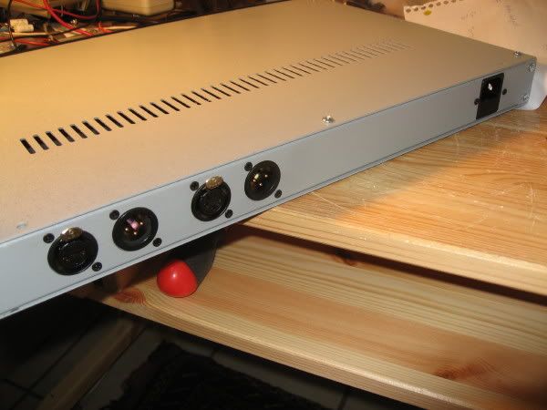
). Or make your own panel. None of it very pretty. I finally solved the problems with the 1RU case and finished this. Thanks to AUDIOX and all who contributed.
I used a Par Metal case, a front panel from Dan, and the 15v PS sold by burdji's DIY General Store in the WM.
The boards are too tall for the case and just a bit too long. The front panel doesn't work the way it was intended.
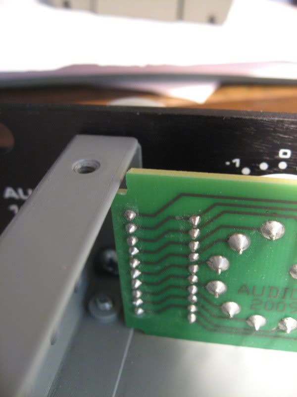
The photos:
I notched the top and bottom edges of one board to fit over the side lips.
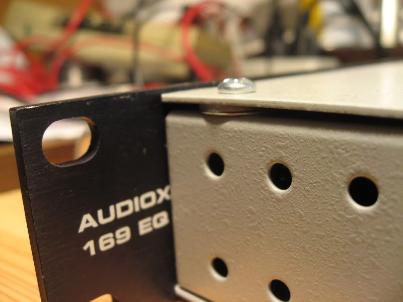
I added a spacer to lift the top to the height of the boards. It fits in the rack okay.
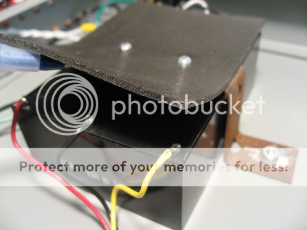
I straped in the PS and clipped the pins. Tight fit! Insulate well.
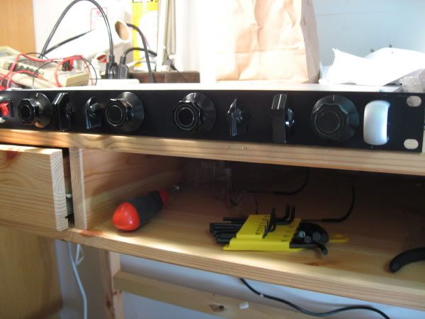
Front of unit. Power switch is on the left.
Back of unit. Top is not lifted in back.
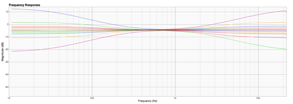
Works great. Boost/cut range of the mastering version.
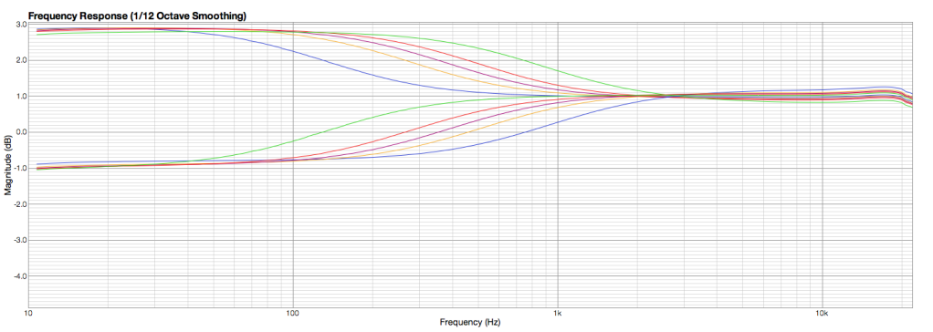
Lo freq selections.
I used a Par Metal case, a front panel from Dan, and the 15v PS sold by burdji's DIY General Store in the WM.
The boards are too tall for the case and just a bit too long. The front panel doesn't work the way it was intended.
The photos:
I notched the top and bottom edges of one board to fit over the side lips.
I added a spacer to lift the top to the height of the boards. It fits in the rack okay.
I straped in the PS and clipped the pins. Tight fit! Insulate well.
Front of unit. Power switch is on the left.
Back of unit. Top is not lifted in back.
Works great. Boost/cut range of the mastering version.
Lo freq selections.
Great stuff Bobine!
Those frequency plots are interesting. I wonder if you could indulge me and test a theory I have. Could you plot one of the low boost frequencies on full boost and see if it changes at all when you change which high frequency band you have selected. I have a hunch that it will change the low band turnover frequency as per this thread: http://www.groupdiy.com/index.php?topic=43089.0 I haven't built the circuit yet and my simulation skills are non existent.
Thankyou in advance!
Similar threads
- Replies
- 22
- Views
- 8K
- Replies
- 3
- Views
- 2K