300vdc plate, 19vdc heater psu

GroupDIY Audio Forum

Help Support GroupDIY Audio Forum:

This site may earn a commission from merchant affiliate links, including eBay, Amazon, and others.

b3groover

Well-known member
Joined
Jun 22, 2004
Messages
359
Location
Lansing, MI
So I got these IPC tube preamps that need 300vdc for the plates and 19vdc for the heaters. Does anyone know of a supply that can do this?

I am not an electronics guru... I know what different components are and I can troubleshoot, but I can't design anything from scratch. I was looking at these Hammond transformers (http://www.hammondmfg.com/300series.htm) and thinking it wouldn't be too hard to take the 300 - 0 - 300 model and use that and maybe take it's 6.3vdc filament winding and put it through a voltage tripler circuit (6.3 x 3 = 18.9) but I have no clue where to start beyond that.

Any ideas?
 
a 300-0-300 is most likely going to get you over the mark depending on your choce in rectifier and filtering. Try www.duncanamps.com and look in the software section for the power supply designer. I would recomend avoiding the voltage trippler and just use a seperate transformer for the filament supply. The choice of solid state versus tube rectifier is really a choice of pregerance. Generaly tubes give a larger voltage drop and have a slower response but a smoother sound. Solid state is faster and leaves a tighter, sharper sound. Although since this is a preamp and everything is class A most likely, you are not going to hear much of a difference. Solid state will allow you to filter the power supply abit more aggressively and get a cleaner supply, which you can hear. You can acheive this also with tubes but generaly this involes coils in the filters and more money. What kind of tubes are in this thing anyways? three 6.3 volt tubes in series or something?

adam
 
It has two tubes, the 5879 and a 12AT7. The 12AT7 is taking 12.6v and the 5879 is taking 6.3v.

I downloaded the PSU designer software but like I said, I'm a moron when it comes to theory. I understand that 120vac goes into the primary, and then 300v comes out of the secondary and then you need to rectify it to smooth it out... but how that actually happens and how you hook it up... I'm lost there.

For instance, on that amp page I linked to before, they have this wiring diagram...

http://www.angela.com/catalog/how-to/single_6v6/princeton.lay.gif

Ok, the AC comes in, goes to a fuse and then to the black wires for the power transformer's primary. Got that. Then the two red wires, which represent the B+, go to pins 4 and 6 of the 5Y3GT... and then what? How do the other tubes get B+? The only wires going to the board are the green (which is one of the filament taps) and the yellow (the other filament tap). I don't get it.

I'm trying to learn this stuff and I'm actually reading these cool books my organ technician gave me that he used when he joined the Navy back in the 1950s to become a radar tech. They're great because it's all tubes!! But I'm not too far in yet.
 
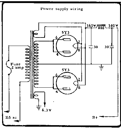
Ok, so let's take this circuit as an example... this is from a Leslie 21H amplifier (of which I own several!) I think I understand how this works, but bear with me...

21Hpsu.gif


Ok, so 115vac comes into the primary through a fuse. The bottom secondary is the heater filament supply... 6.3vdc. That makes sense. The middle filament is the B+ (which is probably around 300v or so... I think the Hammond organs use 350vdc for B+ but I'm not sure).

So the B+ from the transformer gets fed into the cathodes of the 5Y3 rectifier tubes. Ok... that makes sense. Here's where I get confused. The output signal appears on the plate, right? Which is on pins 2 and 8 of that 5Y3. Ok... so that's our rectified signal. But the plates are also connected to the top secondary coil, which is what... another 6.3vdc? Do 5Y3's have a heater filament too?

Ok, so then one side of that secondary (connecting to pin 8 on both 5Y3 tubes) connects to the 0 tap on the B+ secondary. This creates a differential, the cathodes emit their electrons, the plates gather them up, we get a rectified voltage and then a little network of caps and an inductor (which are for what, a little extra smoothing?) and we have 340vdc of B+ (I guess Hammonds use 340vdc B+!).

Am I understanding this right?
 
ok, a little tube info to start, american tubes are numbered in a great way, the first number of the tube name is the heater voltage, 6L6 is a 6 volt heater 12BH7 is a 12 volt heater and 5y3 is a 5 volt heater. The 5Y3 is a tube with an indirectly heated cathode, Pins 2 and 8 are the heater pins which is why they connect to the seperate tap on the supply, it is the 5 Volt tap just for the rectifiers. Rectifier tubes really like to eat up the current so they generaly will have their own tap on the power supply, generaly they are also 5 volt instead of 12 or 6 volts, but there are 12 and 6 volt rectifiers out there. Pin 8 is also the cathode which is where b+ comes out, pins 6 and 4 are the plates. If you look in one of those books of yours they should start explaining how tubes work with the tube diode or rectifier and then go into triodes. It should give you a good bit of information on it works. Otherwise dig around on the web there are alot of sources for tube info. If you are in any hurry to get these preamps running i would recomend haveing your organ guy help you make them. Otherwise just start reading and keep asking questions.
 
[quote author="b3groover"]Ok, so 115vac comes into the primary through a fuse. The bottom secondary is the heater filament supply... 6.3vdc.[/quote]
No, that's 6.3V AC - you can't get DC from a transformer.

So the B+ from the transformer gets fed into the cathodes of the 5Y3 rectifier tubes.
No, the AC (B+ is DC) from the transformer gets fed into the anodes/plates of the rectifiers.

The output signal appears on the plate, right? Which is on pins 2 and 8 of that 5Y3.
No, the output appears on the cathode. Pins 2 and 8 is the filament, which is also the cathode in a directly heated tube.

But the plates are also connected to the top secondary coil, which is what... another 6.3vdc? Do 5Y3's have a heater filament too?
The top secondary supplies 5V AC for the 5Y3 filaments. That winding will also carry the DC output voltage, so you need a seperate heater/filament supply for this type of rectifier.

Am I understanding this right?
Some of it :wink:

Best regards,

Mikkel C. Simonsen
 
Yes, the are old hand-wired, point to point units. It wouldn't be hard to wire the heaters in parallel.

I guess I'm not understanding the whole cathode/plate thing. I thought the output comes off the plate. So this site is wrong?

http://www.svetlana.com/docs/tubeworks.html

All modern vacuum tubes are based on the concept of the Audion--a heated "cathode" boils off electrons into a vacuum; they pass through a grid (or many grids), which control the electron current; the electrons then strike the anode (plate) and are absorbed... The plate, or anode, is the electrode that the output signal appears on.

I must be missing something...
 
[quote author="b3groover"]I guess I'm not understanding the whole cathode/plate thing. I thought the output comes off the plate. So this site is wrong?

http://www.svetlana.com/docs/tubeworks.html

I must be missing something...[/quote]
Yes, that site is wrong. It's talking about audio stages - not powersupplies. But even in audio the output doesn't always come from the plate. In a cathode follower the output is on the cathode for instance.

Just find any electronics book and read the part explaining diodes. The 5Y3 works just like two silicon diodes with the cathodes connected. The rectifier circuit is called a full-wave rectifier.

Best regards,

Mikkel C. Simonsen
 
The cathode acts as an "emitter." When heated up, it emits electrons which are attracted to the positively-charged plate. The control grid, which is interposed between them, controls this flow in a manner analogous to a valve. (And as you probably know, tubes are known as "valves" in Europe). So, a small change in voltage (at the grid) can control a relatively large flow of current (from cathode to plate). That's how the amplification happens. This is the configuration most commonly seen and is known as a "common cathode" or "grounded cathode" amplifier.

Since the amount of current flowing through the tube is controlled by the difference in voltage between the grid and the cathode, it's possible (although less common) to hold the grid voltage at a fixed value and inject the signal at the cathode. This configuration, known as "grounded grid", is not often seen in audio work due to its low input impedance. Its main advantage is low input capacitance, since the grid (which is AC-grounded) acts as a screen between the plate and the input signal. For this reason, the grounded-grid amp is favored in high-frequency work.

If the cathode resistor is not bypassed by a capacitor, then voltage appears across it corresponding to the input signal at the grid. The source impedance at this terminal is relatively low, while the input signal sees only a very high impedance at the grid. This amplifier has no gain--in fact, even when the circuit values are optimized, it always has a slight loss--but this impedance transformation action makes it useful as a buffer. This type amplifier is known as a "cathode follower."

The point of this quick primer is that although the plate is usually used as the output terminal, this is not always the case. The plate or cathode may be used as an output terminal, and the grid or the cathode can be used as the input terminal.

In a power supply, a tube rectifier is acting as a diode or--if it's a fullwave rectifier tube--a pair of diodes with a common cathode. Remember that the plate connects to the higher positive potential! There's no control grid in a diode ("diode" comes from the Greek word for "two", since it's a two-electrode device). A tube, whether it has grids or not, will only allow current flow in one direction. So the tube rectifier--or tube diode, if you prefer--performs a function very much like a solid-state diode, although with a higher forward voltage drop since the terminals are separated by a vacuum instead of a semiconductor junction.
 
Dave and everyone else, thanks for your help. I'm understanding things a bit better now.

I have a really shitty schematic for these. The seller didn't have one, but I found one on a website run by a guy who I bought a Leslie 21H from in Chicago. He has all sorts of esoteric old audio gear. I've emailed him asking for a better scan, but for now this is all I have...

post-17-1089994284.gif


I've labeled what I could decipher. Obviously there's a ground but what's the other one above it (below the B+ pin)? Is that the audio ground?
 
I'm curious what you all think are the pros and cons of ac vs. dc on the heaters. I'm rebuilding the power supply on an diy alembic*f2b* 12ax7 based tube pre.
I have the B+ supply figured out, but I'm not sure which would be betterfor the heater.
The f2b schematics show a 6.3vac heater supply with a hum balance pot.
my trafo has 12vac out for the heaters.

if I go 12ac or reg.12dc on the heaters will parts need to be changed in the preamp circuitry?
 
oh yeah, I guess better isn't really the word I'm looking for...

what adamasd said regarding the B+ regulation was tres useful
faster vs smoother. something along those lines.

Thanks
Sleeper
 
The heater supply doesn't change the sound of an indirectly heated tube like the 12AX7. The only difference is the hum. You may get hum with an AC heater supply - depending on the circuit layout and the tubes. With DC heating you won't get any hum - not from the heaters at least.

Best regards,

Mikkel C. Simonsen
 
Man, these Navy books are very cool! I scanned this B+ power supply schematic for everyone's enjoyment!

post-17-1090037764.gif


Neato! If I want to get 300VDC for the B+ out of that circuit, is it just a matter of replacing the transformer?
 
well a 2A3 regulated power supply, along with a pentode and a gas discharge regulator! why this power supply certainly could work very well for it with a few mods, it would be abit more then just a different transformer, you would have also address the regulator. I would not bother with the regulation, a solid state rectifier with some good filtering afterwords should be more then adequate. The only advantage I really see in a tube rectifier with that preamp is useing a rectifier with a soft start to keep those tubes from going into shock, but thats what standby switches are for. This power supply I would call overkill.

I am in total agreement with the previous comment about rewireing the heaters parallel and save alot of work and go with plain ol 6.3 VAC heaters. It would simplify the power supply and make it much more standard.

adam
 

Latest posts

Back
Top