You are using an out of date browser. It may not display this or other websites correctly.
You should upgrade or use an alternative browser.
You should upgrade or use an alternative browser.
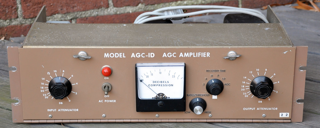
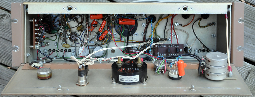
CCA LA 1D Vari Mu limiter..any info on this ?????
- Thread starter gary o
- Start date
Help Support GroupDIY Audio Forum:
This site may earn a commission from merchant affiliate
links, including eBay, Amazon, and others.
I've got a couple of Edcors 8K to 600R, 10W on order for a dual channel gates/teletronix thingo.
Edcor 600:15K input traffos and 15K:15K interstage.
Edcor PSU traffo as well!
Using bits and pieces from various designs.
But basically a sta level/175b with variable threshold and time constants.
Regulated vari-mu and sidechain rectifier, dc regulated heaters.
Pair of 6V6s for output, 6BC8 (initially!) for vari-mu and 6922 or so in the middle.
EZ40 rectifiers x2 for seperated HV each channel.
Triplett meters and maybe somekind of balancing test setup
Point to point wiring (of course!)
I'm sure it will all work together great!
Can't wait to hear it.
dustbro
Well-known member
I think I want to experiment with one of these as well.
I'm gonna grab the output from sowter.
What do you guys suggest for:
T1 (maybe the Allied 6K7VG?)
T2 (sowter 1009?)
L1
What is R36 doing in this circuit?
I'm gonna grab the output from sowter.
What do you guys suggest for:
T1 (maybe the Allied 6K7VG?)
T2 (sowter 1009?)
L1
What is R36 doing in this circuit?
dustbro
Well-known member
emrr said:Voltage will be high with that transformer, and current is far more than required. I'd dig through the Edcor list.
Thanks for the tip! I'll bet the Edcore XPWR103-120/240 would do the trick. and I'm assuming the 15V or 5V taps would be fine for the heaters?
Is there any specific value on that T-pad? or can I use one of those 600r T-pads from hairball?
Great idea about adding the original and LA-1D release times on the rotary switch. Love that!
Would R27 be the threshold adjustment? (this is my first tube project beside the Drip "paint by numbers" la-2 ;D )
dustbro
Well-known member
emrr said:test: can you think of a reason the T pad would be anything other than 600? They also make T and L pads for speaker use.
damn.. I would have studied if I knew there was gonna be a test :'(
Ok... so 600r for audio and 75r for video http://en.wikipedia.org/wiki/T-pad
great! thanks!
pH said:Dustbro, the Edcor XPWR014 looks better to me, you need a 6v winding if you're going with regular AC heaters (I would). With that transformer you could also use a 5v rectifier tube since the winding is there.
I guess I bypassed that one cause I was looking for a 310-0-310. I'm gonna give theXPWR014 a shot. Thanks!
dustbro
Well-known member
Are C17, C18, C19, and C20 really 220uF film caps? Thats huge!
Anyone have a source for them?
Anyone have a source for them?
dustbro
Well-known member
What are the specs of the meter? I see it says SUNSHINE on the top, but i cant find any info on it.
TIA
TIA
Are C17, C18, C19, and C20 really 220uF film caps? Thats huge!
Anyone have a source for them?
those seems like polarized caps.
even the time constant caps are drawn polarized.
in fact they are (or at least drawn) the same all-over.
interesting to see those 220uF caps on the grids of the 12BH7 - what are they for?
dustbro
Well-known member
emrr said:
Ahh... thank you sir.
so those are the silver mica caps that I see in the guts of your pics. Can I assume that everything else in schematic is uF? The designers note is unreadable for capacitance.
dustbro
Well-known member
Would a Sowter CB24 Pi Filter Choke work in here? It's 18 Henry 70 mA
dustbro
Well-known member

for V2 and V3, is this schematic saying that pins 4+5 are tied together and get one side of the tap, and the other side is going into pin 9 (heater center tap)?
thanks!
Similar threads
- Replies
- 372
- Views
- 66K
- Replies
- 5
- Views
- 2K


