New 'ultimate' SSL buss comp clone ;-)

GroupDIY Audio Forum

Help Support GroupDIY Audio Forum:

This site may earn a commission from merchant affiliate links, including eBay, Amazon, and others.

SSLtech

Well-known member
Joined
Jun 3, 2004
Messages
5,447
Location
Florida (Previously UK)
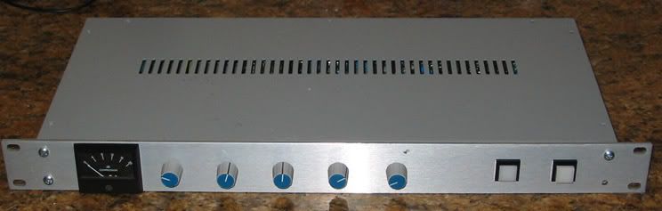
So here's my version of the SSL buss compressor... looks pretty normal from the front:

4kclonefront.jpg


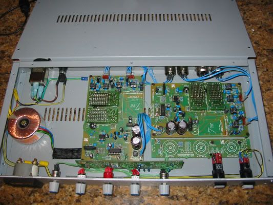
But inside there's a little more than you'd expect...

4kcloneinside.jpg


EDIT: See this post on page 6 for full, condensed build instructions]

Basically it's more like the console buss compressor in one significant way. Jakob's version uses a summed-mono signal which is fed to a single sidechain VCA. phase, polarity and balance affect the detector output. In the console version, two sidechain VCAs feed two detectors, and the higher output is used. Balance, polarity and phase differences are ignored.

This is not to say that Jakob's version is not as good: -it's just different. Jakob himself says that he prefers the sound of his version, but I wanted something a little truer to the original.

Since building two detectors and sidechains meant using two boards; I decided to go one step further. The VCAs I used are the 202XT's, which are each composed of 8 x SIL VCAs for noise reasons. Since they are all used in the same pole, I built the second channel in each and polarity-flipped the signal through it, re-inverting at the end, to re-sum back in the same polarity. (You have to remove one sidechan-summing resistor to prevent the signal nulling...)

The signal thus passes through the VCAs in opposite polarity, and some of the residual VCA distortion is thus canceled. -This is how the SSL 9000 J and K series console center section buss compressor does it: the "Superanalogue" version... except that they do it with half as many VCAs in each pole, since it's getting a little expensive by that point!

In addition, the output summing also increases the output drive capability, and lowers the source impedance... this thing can run full output into about 200Ω without complaining even slightly!

It's built, it's powered up, it's working and the preliminary tests show that it's dead quiet. It's also showing less distortion than my home gear can measure: I'll have to get it reound do Scenaria's and run the Audio Precision on it to get any meaningful numbers!

So here it is. Front panel will eventually be printed with the laser printer/3MSuper77 method, but fo now I'm just glad it's finished!

This is a highly do-able version, there are minimal adaptations needed to two boards to make it work, and a 2-pole ration switch is the big part difference. I'm putting it in my new rack, pictures to follow soon.

Keith :guinness:
 
:shock: :shock: :shock: :thumb: :thumb: :thumb: :thumb: :thumb:
Is this mod doable with THAT2180 ?
:grin:
 
:shock: :shock: :shock:

WOW.

@syn: i think this will be doable with almost every version of the 21xx series - remember 8 of them are used for 1 202 emulation!
Would be a good way to spend my 2159 from that infamous b-box on...

Keith, incredible idea. Excellent work. Any chance that you document your modifications in detail (although you already explained how this works very well!)?

Kind regards
 
It' pretty easy, from memory:

You build one complete "master" unit.

You build an almost complete "slave" unit, leaving out the TL072 on the main board and also omitting the attack/release resistors and caps on the front panel board (but INCLUDING the ratio resistors). Also omit one of the (47k?) resistors on each channel which sums both signals before the sidechain VCA.

Link left input + to right input - on both boards,
link left input - to right output + on both boards.
(Hint: leave the same links on the output until you have dialled out the distortion for each pole VCA collection later! -if you're using pre-trimmed VCAs, go ahead and cross-link the outputs as well.)

Link both boards' VCA CV (at the jumper link next to the 1k resistors that feed the CV to both VCAs on each board is an easy point).

Link both grounds, if they're not linked by a common power transformer 0Volts, or some other method.

Link point 'C' on both boards (output of detector, after the diode).

Wire up the ratio, attack, release and makeup to the "master" unit.

Use two poles of the ratio switch (it's usually a 4-pole anyhow) one to the master board as usual, and a second pole to the four active terminals of the slave ratio control.

If you want to build a quad version of the compressor, or a 5.1 version, just build more slave units and treat each one the same as the first slave unit. For 5-channel units of more, you'd have to get the corresponding number of pole ratio switch (6-pole for 5.1 etc...)

One board (master for example) gets fed left channel, the other gets fed the right channel. Each complete master or slave board assembly is now a mono channel.

Of course, I can also make this particular stereo one switchable between "SSL spec" and "Gyraf spec" by taking the slave unit's 47k summing resistor through a changeover switch to EITHER the slave detector sum input, (SSL spec) or the master sum input (Gyraf spec). That would allow fast comparison between the two modes.

It occurs to me when I think of it, It's no wonder that the Gyraf version threshold is perhaps a little too sensitive: the mod which sums the signals menas that the detector will see a 3dB-to-6dB louder signal than the SSL original version. This can be altered for regular Gyraf clone builders, by just doubling the value of the sidechain summing input resistors.

More thoughts as I have them, -I think that's everything.

[quote author="gyraf"]Wow! That's serious creative thinking!![/quote]
Nah, it's just an adaptation of your adaptation. I'm starting to like the creative option of a switch between "SSL mode" Better for broacast perhaps, where neither side ever exceeds an absolute limit) and "Gyraf mode" (which controls perceived loudness rather better, at teh expense of absolute channel loudness).

It's thanks to you my friend! :guinness: :guinness: (I think that I discussed a lot of this during our first email exchanges some 4 or 5 years ago... it's just taken that long to actually get round to DOING it!!! :wink:

Keith
 
Hi Keith,

congrats to the "head of SSL Clones" ... looks and reads amazing ...

I have a more "simple" question. Most of DIYers (e.g. 99%) do place the main transformer on the right side of the unit. Is there any reason why you placed your mains transformer on the left side of your unit ?

Cheers
JayDee
 
Yes. (well spotted!)

The meter carries no audio and the meter is at the left side of the front panel. Putting the boards close to the rotary controls meant that that the remaining gap was behind the meter. (case isn't deep enough to put the boards behind the meter, so that's where the tranny went!) -Again, there's little or no hum pickup risk from the meter wiring etc.

Also, if you look at the boards, you see that all the audio (except for the VCAs) is at one end. I put that end close to the audio sockets, to keep the lines short. Then look at where the AC comes in to the boards. With having to "turn" the second board with the PAR metal case being a little tight depth-wise, I put the two AC inputs close together. That means one AC delivery point, and only one low-voltage AC run, rather than spread out over a large area.

-There's more inductive hum pickup risk from the low-voltage wiring because there's more current flowing. There's less high-voltage inductive pickup risk, but the power cabling is short, to the point and neatly contained.

I've still yet to use cable ties etc, but there's NO hum pickup at all, so I reckon things must be about right.

Oh yes.. also I increased the 10Ω resistors going to the 78L12 and 79L12 to about 300Ω, to run the regulators cooler. -Looks like it works very well indeed. (Regulators are dropping from 20VDC instead of 29VDC.. I'm using an 18-0-18V transformer.)

Keith
 
Excellent! I have some gssl boards right here, now i will do a master slave unit with the ones i saved some elnas for!!! (one was intended for mastering, the others for bus compress...)
:razz: :thumb: :thumb:
Nice explanations, sounds quite sinple!

Thank you very much!

Kind regards

Martin
 
Keith,
That is very cool man :thumb:

Did you build the 202XT's yourself?

I have enough VCA's to do it & would like to.

Is there a board layout & schematic you could share or point me to...
PLEASE?
I have 2150, 2180 & 2181's... which ones would be best?

Also, it makes sense about the side-chain mix resistors... what value do you recommend for this?

Thanks,
Kevin
 
[quote author="khstudio"]Keith,
That is very cool man :thumb:

Did you build the 202XT's yourself?

I have enough VCA's to do it & would like to.[/quote]
No I didn't, though you could I suppose...
[quote author="khstudio"]Is there a board layout & schematic you could share or point me to...
PLEASE?[/quote]
I don't know of one, you have to use close-matched resistors, so it's still not entirely easy...
[quote author="khstudio"]I have 2150, 2180 & 2181's... which ones would be best?[/quote]
I don't know, though I'd imagine 218x are better then 215x, and pre-trimmed is the ONLY option if you don't have a good distortion analyser.
[quote author="khstudio"]Also, it makes sense about the side-chain mix resistors... what value do you recommend for this?[/quote]
Stary by doubling them. (47k = 100K) That will give you 6dB better range. If that's not enough, try doubling again (220K) that'll be 12dB more. As long as they're all the same, the precise accuracy of the doubling isn't too critical to my mind.

Keith
 
HI Keith,
Great Job :thumb: You make everyone smiling :grin:

I was thinking of something like this, but I am not good in electronics so I am still confused.

I am thinking of building two master cards in same unit but with only one input channel per card. By this I get two mono or one stereo channel.
Do you think it is a good idea. If it is good How can we separate & combine attack, release & ratio switches.

& some more can we add some more ratios to this as this has only 3 selections. like 1:2,4,6,8 & 10.

regards
 
Brilliant work, Keef!
BrooklynPilsner.jpg


I was considering doing a stereo link on my tube compressor by mixing the signals into the sidechain amplifiers. I discussed this with PRR and straight away, he pointed out the pitfalls. For me, it was one of those "slap your forehead" moments; it became apparent immediately that linking after the rectifiers was definitely the way to go. It works as a sort of "absolute value" circuit and ensures that the GR of both channels tracks the highest signal amplitude present in either channel, regardless of polarity or phase.

I'd write more, but I just remembered that I have a pizza that's been in the oven a little too long. I must be going!
 

Latest posts

Back
Top