TL783 Bypass Reference Pin Or Not

GroupDIY Audio Forum

Help Support GroupDIY Audio Forum:

This site may earn a commission from merchant affiliate links, including eBay, Amazon, and others.

Samuel Groner

Well-known member
Joined
Aug 19, 2004
Messages
2,940
Location
Zürich, Switzerland
Hi

On a recent mic preamp design I used a TL783 to supply the eight channels with phantom power. As proposed in the data sheet, I didn't bypass the reference pin as one would do with LM317 et al. The voltage divider impedance for the reference pin was chosen such that it draws the minimum output quiescent current and both smoothing capacitors and secondary transformer voltage were generously specified.

When watching the output of the voltage regulator on the 'scope I noticed that I got much more (though still below 5 mVpp) low-frequency noise/ripple than on the other six supply lines using more standard regulators (both fixed and adjustable).

The RC filter right before the two 6k8 resistors obviously heavily suppressed the noise such that it is not a problem in practice. But as the addition of a capacitor and protection diode isn't much of a hassle, I thougth if there are any opinions/experiences out here?

I see that Bo Hansen seems to use bypassing: http://web.telia.com/~u31617586/#48 volt phantom power supply

Samuel
 
Hello Samuel,

I use 1000 mfd 100V input cap.
150 ohm adj
5.6k 2W unbypassed.
100 mfd 63V O/P.
Then direct or via series R to cap of choice feeding 6.8k resistors.
Works well.

Sorr
 
Thanks for your response--my circuit is similar, just with lower input smoothing capacitor (1000 uF seems a bit highish considering transformer efficiency). I didn't mean to say it did not work well, just thougth perhaps someone allready measured the difference (the design is allready hooked up, so I'm too lazy to unscrew it again...).

Samuel
 
Personally, I prefer not to by-pass the reference input in order to minimise the regulator output impedance over the frequency range. This reduces interaction between channels fed with PP. Local R-C decoupling of each channel's PP rail before the 6K8s is advisable.
 
Samuel Groner said:
... just thought perhaps someone already measured the difference (the design is already hooked up, so I'm too lazy to unscrew it again...).

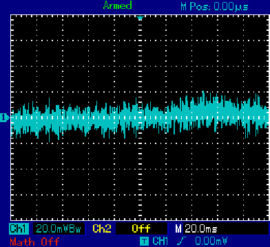
Without cap:
TL783_no_bypass_ref_pin.gif


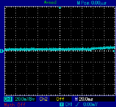
With cap:
TL783_bypass_ref_pin.gif


Circuit was a full-wave voltage doubler with a 470uF capacitor at the input of the Vreg but with no cap at the output so the full effects of the capacitor on the adjust pin could be seen.

There have been more recent discussions about the merits of putting a cap there. Douglas Self mentions that it is "essential" to put a cap there as without it the ripple is amplified along with the reference voltage.1 Never thought of it that way before, but it looks more like noise than ripple to me.

Boswell said:
Personally, I prefer not to by-pass the reference input in order to minimise the regulator output impedance over the frequency range.

Looks like the poster hasn't been around for some time, but does anyone know what frequency range was being referred to? Seems as though phantom should be DC?

1. Small Signal Audio Design page 539
 
With a couple of years more background in audio electronics I see no reason to not bypass. The AC output impedance will actually decrease, not increase. More feedback = lower output Z.

Samuel
 
I use the TL783 for my phantom supplies:

http://www.groupdiy.com/index.php?topic=42745.0

I use a much larger smoothing cap than you, 4700uF which, allowing for a maximum load of 100mA should have about 200mV of ripple across it. I use a 50VAC input so the dc out from the smoothing cap is about 70V giving a comfortable 20V input output differential. Under these conditions the data sheet says the ripple reduction should be about 60dB so we can expect about 0.2mV of output ripple. The first time I built this circuit the output ripple was very low but it was masked by a lot of broadband output noise. A 10uF directly across the output cured this. Using this circuit with a 70dB gain mic pre I was unable to detect any difference in the output noise of the mic pre with the phantom power on or off (and in the off position the phantom power was completely disconnected).

Clearly the 10uF makes a lot of difference to the output noise and I would recommend always fitting this. I have not tested whether bypassing the ADJ provides any additional improvement simply because I have not found it necessary.

Cheers

Ian
 
ruffrecords said:
I use a much larger smoothing cap than you...

My current requirements are much more modest than yours (I did mention voltage doubler ;)). Not looking to power every mic I own!

ruffrecords said:
Using this circuit with a 70dB gain mic pre I was unable to detect any difference in the output noise of the mic pre with the phantom power on or off (and in the off position the phantom power was completely disconnected).

Says as much about the common mode rejection of your preamp as anything, doesn't it?

ruffrecords said:
Clearly the 10uF makes a lot of difference to the output noise and I would recommend always fitting this. I have not tested whether bypassing the ADJ provides any additional improvement simply because I have not found it necessary.

Of course - and any real-world implementation would have the usual local filtering at the XLR as well.

But the measurement seem to suggest that Doug Self is right - you're simply amplifying whatever is sitting on the reference voltage. To me there's some satisfaction in tackling it at its source.

Anyway, what's a couple of pads in the scheme of things? You can drop a 50 cent cap in or not...depending on your religion...
 
mnats said:
ruffrecords said:
Using this circuit with a 70dB gain mic pre I was unable to detect any difference in the output noise of the mic pre with the phantom power on or off (and in the off position the phantom power was completely disconnected).

Says as much about the common mode rejection of your preamp as anything, doesn't it?

Even if the CMRR of my preamp was perfect the real factor that determines how much phantom noise gets through is how closely matched are the two 6k81 feed resistors (which you do have some control over) not to mention how balanced is the load on each presented by the mic electronics (which you have no control over)

ruffrecords said:
Clearly the 10uF makes a lot of difference to the output noise and I would recommend always fitting this. I have not tested whether bypassing the ADJ provides any additional improvement simply because I have not found it necessary.

Anyway, what's a couple of pads in the scheme of things? You can drop a 50 cent cap in or not...depending on your religion...

Not a lot, but you do need some extra protection circuitry as well to guard against load transients.

Cheers

Ian
 
in the datasheet there is the following text:

"Adjustment-terminal capacitors are not recommended for use on the TL783 because they can seriously degrade
load transient response, as well as create a need for extra protection circuitry. Excellent ripple rejection presently
is achieved without this added capacitor."

 
but since in a phanthom supply there is no very often required to the IC regulator having a fast transients feature for the presence of the out RC filter, I would add the cap in the feedback network.
 
the 6.8k resistors and the cap of the out RC cut off the mid-high frequency load's currentsso the IC reg have not to regulate these currents. to be precise.
 
I use a much larger smoothing cap than you, 4700 uF which, allowing for a maximum load of 100 mA should have about 200 mV of ripple across it.

I would not recommend the use of such large smoothing capacitors. They make the peak current going trough transformer/rectifier unnecessarily high. This will pronounce resulting magnetic field which is *much* harder to get rid of than a bit of voltage ripple. I consider it good design practice to size the caps for 1 V to 2 V ripple. More for high voltages, less for lower ones (to get decent efficiency).

The first time I built this circuit the output ripple was very low but it was masked by a lot of broadband output noise. A 10 uF directly across the output cured this.

Clearly the 10 uF makes a lot of difference to the output noise and I would recommend always fitting this.

The output capacitor is required for stability. Without it the regulator will oscillate (which does not necessarily show up as nice sine wave). This issue is not related to what we're discussing here.

But the measurement seem to suggest that Doug Self is right--you're simply amplifying whatever is sitting on the reference voltage.

Of course. A voltage regulator is not much else than an opamp, configured as noninverting and fed from a DC voltage reference. The feedback network sets the output voltage. Both noise and PSRR is multiplied by the noise gain at the output; with the bypass capacitor noise gain drops to unity at AC and hence noise and PSRR is proportionally improved. By about 32 dB in this particular case.

In the datasheet there is the following text:

The datasheet's always right ;). That's why I didn't put the cap there some years back. But the datasheet is not smarter as the people who wrote it...

They can seriously degrade load transient response.

I must admit some doubts about this; most regulators show better transient response with more feedback. In any case there will be no significant transient load with a phantom power supply as noted by ppa--they're talking about things like from 5 mA to 500 mA in 1 us.

Create a need for extra protection circuitry.

True--one diode more, see LM317 datasheet.

Excellent ripple rejection presently is achieved without this added capacitor.

What's "excellent"? It's surely much better with the capacitor. Figure 4 of the datasheet shows that with the cap it is more than 30 dB better; the cap effectively converts the regulator from the 48 V output voltage case to the 1.27 V output voltage case at AC. That's the same as said above--noise gain goes from 32 dB to 0 dB, so noise and PSRR improves by 32 dB.

Samuel
 
I recently looked at HT regulation using a TL783 in a G9 supply.

Just some thoughts to be aware of.

1. The TL783 requires quite a decent load before it regulates properly. You might want to permanently "throw away" some current using a simple resistor to ground to cope with overvoltage before phantom power to the first mic is connected.

2. Larger filter caps do not always mean less noise, as they mean higher currents during charging (and diode switching noise). Possibly better to use a 2 or even 3 stage passive RCRCRC filter than one big single stage RC filter.

3. As has already been pointed out: with phantom power, the matching of your 6K81 resistors is probably more critical than anything else. A 1% match is only 34dB CMRR worst case (1.01/0.99 - 1) for noise associated with the 6K81 resistors. A 0.1% pair of matched resistors increases this source of CMRR (to 1001/999 -1) so potentially by another approx 20dB for just a few pennies more. So even if your 48V has pretty lousy PSRR for 50Hz you can possibly improve quite quickly how much of that noise makes it into the signal by improving this matching.

4. It isn't just the volume of the noise. You also have to look at the noise spectrum, especially under load. When testing out an off board supply to reduce mains hum on a G9 build, I "improved" the noise level significantly by rearranging the passive 470ohm /220uF filter after the regulator. My thinking: surely silicon is better than passive filters? I was wrong. Looking on a spectrum analyzer at the power supply noise when the G9 was actually passing signal showed me that the spectrum of the noise under load had altered significantly, so although 50Hz regulation was greatly improved and there was no hum under load, higher (audio) frequency regulation suffered when one channel sucked current, resulting in cross talk of audio signals between the two channels via the HT. Same could potentially happen between mic channels via the phantom power (although to a lesser extent). Regardless of the theory the point is that you have to measure the supply in use under load.

5. The load from a mic can vary greatly due to the signal being carried with the power. A typical mic can draw 2mA. So now you only have 48v -2mA * 6k8 => ± 34V at the mic input. Where's your super duper 48.000V DC regulation now? Also what if the mic's current draw changes by 1% when it gets hit with a large signal. That'll also show up as modulation on the effective supply voltage via the 6K8 resistor.  So again, you'd need to test whether any of these "improvements" translate into real improvements in practice with a mic passing real audio.
 
MeToo2 said:
3. As has already been pointed out: with phantom power, the matching of your 6K81 resistors is probably more critical than anything else. A 1% match is only 34dB CMRR worst case (1.01/0.99 - 1) for noise associated with the 6K81 resistors. A 0.1% pair of matched resistors increases this source of CMRR (to 1001/999 -1) so potentially by another approx 20dB for just a few pennies more. So even if your 48V has pretty lousy PSRR for 50Hz you can possibly improve quite quickly how much of that noise makes it into the signal by improving this matching.

Rather than trying to find an (expensive) source of 0.1% resistors I simply hand match 1% ones using a DVM. It does not matter about the accuracy of the meter either just so long as it is repeatable. I find it relatively easy to select pairs within an ohm of eachother.

5. The load from a mic can vary greatly due to the signal being carried with the power. A typical mic can draw 2mA. So now you only have 48v -2mA * 6k8 => ± 34V at the mic input. Where's your super duper 48.000V DC regulation now?

IIRC the official spec for phantom power is 44 to 52 volts dc. You can get well within that without using trim pots and as has been said, the noise on the supply is more important than its absolute dc value.

Cheers

Ian
 
ruffrecords said:
MeToo2 said:
3. As has already been pointed out: with phantom power, the matching of your 6K81 resistors is probably more critical than anything else. A 1% match is only 34dB CMRR worst case (1.01/0.99 - 1) for noise associated with the 6K81 resistors. A 0.1% pair of matched resistors increases this source of CMRR (to 1001/999 -1) so potentially by another approx 20dB for just a few pennies more. So even if your 48V has pretty lousy PSRR for 50Hz you can possibly improve quite quickly how much of that noise makes it into the signal by improving this matching.

Rather than trying to find an (expensive) source of 0.1% resistors I simply hand match 1% ones using a DVM. It does not matter about the accuracy of the meter either just so long as it is repeatable. I find it relatively easy to select pairs within an ohm of eachother.
0.1% resistors cost me a euro each including tax. Sure, hand matching components works for DIY. How much do you charge for you time? ;)


IIRC the official spec for phantom power is 44 to 52 volts dc. You can get well within that without using trim pots and as has been said, the noise on the supply is more important than its absolute dc value.

Cheers

Ian
The wide voltage spec may suggest that simple cascaded RCRCRC filters may have some advantages over silicon regulators, especially at higher frequencies. You could have a common chain followed by a final dedicated RC per channel.

As for noise and filtering, don't forget signals injected back into the power supply output from other channels, or elsewhere. It's a two way street. This was the original point Boswell was making & which Mnats asked to be clarified: reduced output impedance of the psu over the whole frequency range can help reject signals fed back from other channels into the output of the PSU (crosstalk = noise too). This may or may not be significant compared to noise generated by the PSU itself. 78xx series are particularly bad at rejecting/regulating higher frequencies. The TL783 also increases output impedance with frequency although not too badly. Ripple rejection in the TL783 also reduces with frequency, unlike most passive filters (which is perhaps why the 10uF output bypass cap can appear to help, at least over a limited frequency range of 10Khz - 100KHz according to the data sheet). Mnats already suggested doing further filtering at the XLR, which is sensible. A humble LM317 (plus protection zener) is probably also well worth investigating as an alternative for a phantom supply, but that's off topic.

Here's a link to the measurements I made on a TL783 HT supply on a g9 with various different filters, physical layout, and input transformers, conducted by terminating the left channel with mic impedance and injecting pink noise into the right channel: note the trade off of vastly improved low frequency regulation (<<500Hz) on the left channel compared to poorer overall rejection of cross talk (hump at 1KHz) in the first two graphs. Noise is a funny thing and rarely follows convenient theory. My new improved PSU was worse overall. But simply physically moving the old PSU off board was a great improvement for 50Hz mains hum and its harmonics (3rd graph).
http://i958.photobucket.com/albums/ae69/MeToo2_Prodigy/psu_noise_tests/noisextalkoriginalpsuoep.png
http://i958.photobucket.com/albums/ae69/MeToo2_Prodigy/psu_noise_tests/noisextalknewpsuoep.png
http://i958.photobucket.com/albums/ae69/MeToo2_Prodigy/psu_noise_tests/noisextalkextpsuoep.png
 
I would not recommend the use of such large smoothing capacitors. They make the peak current going trough transformer/rectifier unnecessarily high. This will pronounce resulting magnetic field which is *much* harder to get rid of than a bit of voltage ripple. I consider it good design practice to size the caps for 1 V to 2 V ripple. More for high voltages, less for lower ones (to get decent efficiency).

In practice this is not a problem. The peak currents are not very high because they are limited by the transformer resistance which I have measured as 20 ohms. A simple simulation with perfect diodes and a capacitor with zero ESR shows that even with the full 100mA design load, the peak transformer current is no more than 500mA. With a 10mA load it is a mere 120mA. In the real world, with real diodes and capacitor, the currents will be even less.

Cheers

Ian
 

Latest posts

Back
Top