[BUILD] 1176LN Rev D DIY

GroupDIY Audio Forum

Help Support GroupDIY Audio Forum:

This site may earn a commission from merchant affiliate links, including eBay, Amazon, and others.
Hey Sintech thanks! Got it working already! I was missing one wire to pad 7. A very important one lol. Just need to finish a few odds and ends and bolt her into the rack, :) After calibration that is...
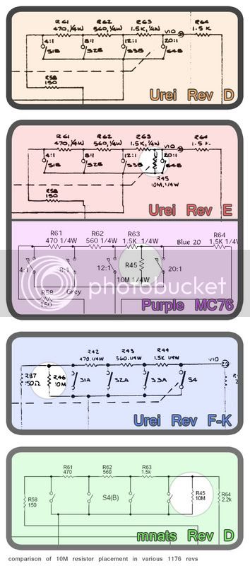
That 10 meg resistor is on the 20:1 side of the switch according to the schematic.

Thanks again,
John
 
Congrats :)

The 10 meg is a buffer for all buttons in, it's as Urei wired it on a 70's 1176LN.
 
sintech,

Awesome diagram--this will surely help!  Thanks.


Regarding the 10M resistor:
I've noticed that the placement of this component varies widely from schematic to schematic.

Where is the best place to have this resistor?


Check it out:

1176_TenMeg.jpg
 
Mine seems to work fine at the mnats position. BTW here are some pics

11761

11762

1176tranny

It works and sound great even with the radio shack tranny. :)
My meter pegs easy in +4 and +8 tho. Long before 0 vu in protools.
This project was alot of fun! Thanks for all the help once again.
Now for that input tranny  :green:

John
 
[quote author="Skylar"]sintech,
Regarding the 10M resistor:
I've noticed that the placement of this component varies widely from schematic to schematic.

Where is the best place to have this resistor?
[/quote]

if you look carefully, you can see that regardless of how it is drawn, electrically there are only three choices:

no resistor at all - (urei rev D)
from the junction of r63 and r64 (aka wiring point 20) to the sidechain rectifier (aka wiring point 21) - (urei rev E, purple mc76/77, mnats rev D)
from the junction of r87 and r42 to the sidechain rectifier - (urei rev f-k)

and really the difference between the last two is very minor when you consider the combined resistance of r42, r43, r44 vs the 10M resistance of r46. you don't want to leave the connection to the sidechain floating when all the switches are open, so r46 should be there, but putting it in either place will stop any crazyness from happening.

ed
 

Click for big.

Got half of my 1U stereo version running. The bakelite version of the UTC Ouncer is in there temporarily. The Cinemag output transformer had to shed its end bells to fit.

In order to fit all the controls on the front panel I had to do some juggling. Far left is a Clarostat bridged T-pad. There's a DPDT toggle to select GR or Output metering for the Sifam AL19. Pull the Attack knob to turn off the Gain Reduction. And the Alpha 5 position switch is hard wired with the divider resistors for ratio selection with Slam for the fifth click.

Sounds very sweet. How's everyone else's build going?
 
Mine works perfectly. It has also passed at least a 30 hour burn in. The output transistor runs hot. But I have seen alot of older gear have burn marks on the circuit boards from normal use. (After many years) Usually resistors tho. I should measure it's temp to see if it is in spec for that part.
I can't use mine in the studio yet tho cause I only have the 1:1 radio shack input transformer. Waiting to hopefully get one from Edanderson when they arrive. The frequency response is not so great as you can imagine.
I still have to doctor a couple things... Like the VU lamp I have is the Sifam 12 volt. I used 2 100 ohm power resistors in series to drop the voltage. (200 ohm) but I still have 12.9 at the lamp so I have to order a few extra values. But I am close. I have 34 volts AC from power tranny.
And I learned a lot on this project! Thanks again for making it available.

:thumb:

Also if you are using Kato's BOM and are using pushbutton switches you will need 1 extra resistor. You'll need a 8.2k 1/4 watt (R77)
 
Upon actually following the calibration procedures outlined in the urei docs I encountered a never-ending circle of confusion. For instance, the more I tinker I realize that the procedure outlined in 5.3.2 is sort of dependent on that of 5.3.3 and so on.

Does the procedure to adjust the null and tracking require the complete removal of R44? On page 60 of the urei pdf, there is a document entitled "Meter Calibration" the relationship between R75, R71, and R44...that is a sensitive dynamic that one there, especially when you throw the R44 as a trim pot into the mix.

Also, I read in the G thread that shorting terminal 22 to ground is the same as placing attack in the off position (as mentioned numerous times in the docs). Does this apply to the rev D board?

Can the bias adjustment be made with the meter trim pots whacked out (or centered, say)?

I need to finish reading the rev G thread one of these days...sorry.
 
MNATS: How's everyone else's build going?

Its getting there. I am playing the waiting game.

Some of my transistors didn't meet the hfe spec so I am waiting on some new ones.

I didn't realize matching FETs was going to be a big deal for a stereo unit, so I am waiting for a batch of FETs too.

Waiting on the input attenuator from a group buy. Thanks ap123.

Waiting on my cinemag output transformer order. They seems a little absent minded with regards to small orders.

I tried to cut corners on a few things and they didn't work out, i.e. meters and a power transformer, so I just got that straightened out.

My only concern now is the input transformers.
 
Someone (thank you) pointed out to me that the Lorlins on my parts list have solder eyelets rather than PCB pins. I'm sorry, I have no idea how I did that.

I updated my parts list. (I still have not ordered the Lorlins; current part is still not verified.)

Reportedly, you can cut the eyelets off and insert the pins into the PCB but bending is required.

Anyone know of a part that fits more accurately, please let me know.
 
I think I have something in wrong. I built two boards and both behave the same; when I send 1khz as instructed in the calibration instructions and turn the bias cw until 1dB drop, when I change ratio something is wrong. There is no limiting or sometimes there is, sometimes not; intermittent only with the change of the ratio switch. Before I tried calibrating I had it working on a few of the ratio settings. Also, even after being powered on for 15 minutes my output level will climb with the test tone; very slowly. Makes the bias adjustment odd. I really think I have something together wrong.

Dumb question yeah yeah... but is the actual limiting behavior/functionality of the 1176LN dependent on the calibration of the meter circuit? That is probably the question of the month for me.

BladeSG, thanks...it had been so long since I had actually read the mnats rev d page that I prematurely soldered in R44 so I guess I'll be removing that.
 
Sorry to interrupt, ap123, but...

Is anyone currently trying to get a hold of Cinemag CM-96731 output
transformers? I was thinking of buying direct, but if someone has an
order pending, I would like to get in on that as opposed to ordering
a single transformer from Cinemag.

Anybody?
 
Is anyone currently trying to get a hold of Cinemag CM-96731 output transformers?

I kept missing the boat on group orders so I ordered 2 direct from them. Did the whole thing with email and paypal. They were cool and didn't give me the "blow off" becuase it was a small order. I did have to remind them a couple of times though. I have not recieved it yet, but it has not been that long since I ordered. I believe they just whipped up a batch so they may have still have some around.
 
[quote author="kato"]Someone (thank you) pointed out to me that the Lorlins on my parts list have solder eyelets rather than PCB pins. I'm sorry, I have no idea how I did that.

I updated my parts list. (I still have not ordered the Lorlins; current part is still not verified.)

Reportedly, you can cut the eyelets off and insert the pins into the PCB but bending is required.

Anyone know of a part that fits more accurately, please let me know.[/quote]

The Lorlins do fit if you cut the eyelets off. You do have to bend the tabs out a little bit though. I have one question regarding these though. The PCB for the switch that has 4 pins in the center is clearly marked as to the direction that the switch is mounted. The other PCB, however, has no markings for mounting orientation. Can anyone clue me in to this?

Cheers,
Zach
 
[quote author="usekgb"]
Can anyone clue me in to this?
[/quote]

Maybe you can decipher this image from Mnats wiring page:

1176_rotary_wiring_meter_ratio_overview.jpg


[quote author="usekgb"]
You do have to bend the tabs out a little bit though.
[/quote]

That doesn't sound too bad. Thanks for the input.
 
[quote author="usekgb"]The other PCB, however, has no markings for mounting orientation. Can anyone clue me in to this?

Cheers,
Zach[/quote]

I too was a bit confused by this. One board has the "A" pin identified but the other does not. I assumed that because the alignment wasn't noted that it didn't matter. Those are the kind of stupid assumptions I make on an hourly basis, though.

I just cut the tabs off and bent them out a little...that worked excellently.
 
kato said:
[quote author="usekgb"]
Can anyone clue me in to this?

Maybe you can decipher this image from Mnats wiring page:

1176_rotary_wiring_meter_ratio_overview.jpg


I'm just a little confused on this Lorlin 2pole 6pos switch. It appears to have 4 more contacts along the outside ring, and it can me mounted two different ways. Would it matter if I get the "A" and "C" contacts reversed, or will it still work just fine?

Cheers,
Zach
 
[quote author="usekgb"]
I'm just a little confused on this Lorlin 2pole 6pos switch. It appears to have 4 more contacts along the outside ring, and it can me mounted two different ways. Would it matter if I get the "A" and "C" contacts reversed, or will it still work just fine?

Cheers,
Zach[/quote]

I'm very interested to know this...perhaps that's why I can't bias this thing to save my life. Maybe my ratio switches are backwards. That'll be fun to take out... :?
 
Back
Top