ChrioN
Well-known member
Since the PCB only got one ground connection each for the input and output XLRs, are you guys just linking the two pin 1's of the input XLR pair and then just connect one of the pin 1 to the PCB?


Just ground the input, because the pin1 of the input is the 0V of the PCB like the 0V of the OutputWhy not also connect the two Output Pin 1s also to chassis/earth (i.e. signal) ground?
So, I'm sorry to ask again, but I just can't get rid of the hum in my SSL
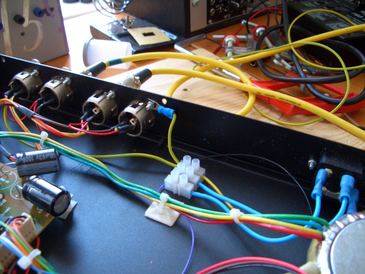
") me, the casing of the XLR's are already grounded to the bare metal of the case (from when you cut out the holes) so why ground one XLR to the case again? Is that creating another ground loop?
me, the casing of the XLR's are already grounded to the bare metal of the case (from when you cut out the holes) so why ground one XLR to the case again? Is that creating another ground loop?Enter your email address to join: