Ramped phantom power project

GroupDIY Audio Forum

Help Support GroupDIY Audio Forum:

This site may earn a commission from merchant affiliate links, including eBay, Amazon, and others.

barthman.de

Well-known member
Joined
May 26, 2007
Messages
98
Location
Erfurt / Germany
I'm building a housing solution for 4 Telefunken V672 Mic/Line preamps. In addition to the preamps the housing includes a Telefunken N624 (24 V / 2 A) PSU.

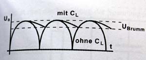
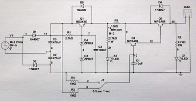
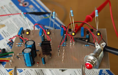
I want to use this PSU to power a second preamp unit which I'll build later (also with 4 preamps). Now I need a second PSU for phantom power. Here in the forum I found two circuits which I've combinated (ramped phantom power and voltage doubling). Here is my circuit (to power one mic) and a photo of the prototype (to power 4 mics).

phantom.jpg


phantom3.jpg


Now my questions:

1. The PSU works fine (48 V on output ;-) but I'm a beginner in electronics so if somebody have improvment suggestions let me know before I grill my Neumann mic :?

2. The 2k7 resistor (1W) (R2) before the LED is very hot. (I can't touch it) The resistor value seems ok for me (48V-2,2V=45,8V; 45,8V/0,02A= 2.290 ohm; 45,8/2k7=0,017A*45,8=0,779W). Is this ok or is there a problem?

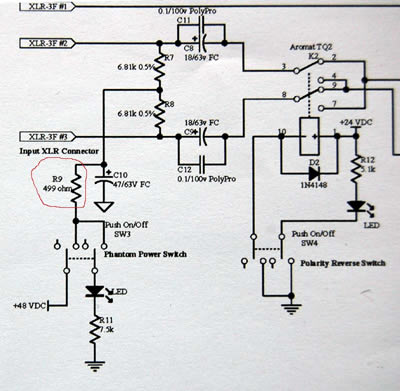
3. On some preamp designs there is a resistor (450 - 500 ohm) before the standard 6k8 resistors (see below). Which function has this resistor?

phantom2.jpg


Thanks for your reply.
 
(2) resistors run hot that close to their ratings (0.78W in a 1W resistor). It's no surprise you don't want to hold your finger on it. It sholdn't be a problem but overkill is not a bad idea (a 2W or 3W would be fine in that position).

Also, you could source a more efficient LED and run less current through it---that's a pretty inefficient way to have an indicator lamp.

(3) the function of the 499 ohm resistor is to provide a lowpass filter along with C10, to reduce the noise/hum that may be present in the +48V.
 
thanks for your answer.

[quote author="bcarso"] Also, you could source a more efficient LED and run less current through it---that's a pretty inefficient way to have an indicator lamp. [/quote]

Yes you are right. There is a lot of heat. But how can I wangle this? A parallel resistor to r2 will lower the voltage on output. So I must adapt r9 to get 48V. Another idea?

[quote author="bcarso"] (3) the function of the 499 ohm resistor is to provide a lowpass filter along with C10, to reduce the noise/hum that may be present in the +48V. [/quote]

Oh yes I see, it is the same funktion like r1.
 
Take care about R9! If you draw a max of 15mA for the mic, + 20mA for the led, that means 1.68 Watt, a bit much for your multiturn trim pot isn't it?
 
Nice circuit! :green:

What the heck is R9 for? I don't see any good purpose. Why such a low value for C4? A tantalum is probably a good idea at this location, btw.

>>>I would replace r2 with a 6.8K...
I believe that's what I suggested in the text. Don't think you need anything bigger than 1/4W in that case.

>>>it is the same funktion like r1.
Uhh, not really the main function of R1. Read here, see the comments about "Rs".

Glad to see someone else using the ckt. At the time I first showed it, I felt kinda like it was poo-pooed for not having enough isolation from the PS.

HTH!
Charlie
 
>>>What the heck is R9 for?

R9 ist (or was :sad: ) to regulate the voltage to 48 V (see zeners 24V+27V= 51V) But if I change R2 to 6K8 I think I need a higher value for R9 too, to get 48V on output.

>>>Uhh, not really the main function of R1. Read here, see the comments about "Rs".

(Thank you for the site - it helps me to understand.) But I thougt R1 in union with C4 is to towel the DC and that reduce the hum isn't it ? And that's the same what R9 and C10 do on the second image (reduce the hum). The value for R1 and C4 I took from here:

http://www.tangible-technology.com/power/Phantom_frying.html

>>>Take care about R9! If you draw a max of 15mA for the mic, + 20mA for the led, that means 1.68 Watt, a bit much for your multiturn trim pot isn't it?

there I had no problems up to now. but I had no mic on output, maybe I should add a resistor parallel to the output to test it.

Ok. I'll try some changes. :roll:
 
>>>R9 is to regulate the voltage to 48 V
But then your output voltage is dependent on current draw. Higher draw = more V drop across that resistor. That defeats the purpose of the regulator and is poor design, imo. 100 Ohms isn't much and are often used as "fuses" in the event of a short, but don't use a pot, use a fixed resistor. Maybe you think you need this for isolation on each load? A better plan is separate smaller regulators per output if you feel you must. Use two 24V zeners and leave out the 100 Ohms. Lots of gear has less than 48V output anyway and clean Phantom Power is more important than having exactly 48V.

>>>R1/C4 is to towel the DC and that reduce the hum
Took me a minute to figure out what you mean by "towel". I think you mean to say "clean up". The article explains it. The exact function of the components is a little different in these two different circuits. C4 does help reduce noises, but more to stabilize the reference voltage across the zeners which keeps the output from Q1 more stable. In some ways its the same thing but if I remember correctly, small values of capacitance at C4 "look" like big values would if connected from the emitter of Q1 to ground. But as I said before, I think 100nF is TOO small. Your value for R1 is probably good.

>>>I had no problems up to now. but I had no mic on output, maybe I should add a resistor parallel to the output to test it.

A good plan. Lots of circuits will appear to work without load, but things change drastically with a load. A burned resistor will cost a lot less than a burned Neumann. :shock:

Best Regards!
Charlie
 
>>>Took me a minute to figure out what you mean by "towel"

:grin: in German also the meaning of evergreen is needle tree :grin:

here a little picture:

diagram.jpg


mit C = with capacitor
ohne C = without capacitor
U Brumm = U hum

I think we mean the same.

With two 24V zeners, 6k8 and without R9 my programm calculated 46,8 V that seems ok (standard +/- 3V). I've bought a ready build V72 Rack (HE Studiotechnik) and there is also less than 48 V on output.

What value would you take to "simulate" a mic? 4k7 seems ok for me .

Should I change c2+c3 to long life capacitors maybe 470uF/400V/105°C (now 100V)?

lg Sebastian
 
>>>Hum...I think we mean the same.

The dominant noise there is from the zener or zeners in this case. I'm told its like white noise.

The 6k8 suggestion is only for the dropping resistor of the LED...R10 or R2.

>>>c2+c3 to long life capacitors maybe 470uF/400V/105°C (now 100V)?

Long life => Good idea.
470uF => Okay.
400V => Higher voltage generally means higher internal impedance. Get as much voltage as you need plus a little extra, no more. 100V should be fine.
105°C => Usually an indicator of a higher quality cap, in my experience.

Stick with Panasonic or Nichicon if possible.
 
"With two 24V zeners, 6k8 and without R9 my programm calculated 46,8 V that seems ok "

Q2 and Q3 add their own junction voltage (0,6V each) so 24+24 =48, 48 -0,6 - 0,6 = 46,8...
If you want 48V, just add another 1,2 zener, or 2 regular diodes....


"What value would you take to "simulate" a mic? 4k7 seems ok for me "

4K7 will draw 10 mA so that's realistic... The maximum load that a phantom psu is suposed to see is 15 mA, so you could use a 3K3...

I agree with SonsOfThunder, 100nF for C4 may work, but is way too small...
You don't have a lot of filtering in this thing...
 
>>>Q2 and Q3 add their own junction voltage.

Sorry, no. Look at the ckt again. The path from the regulator output to the phantom output is only through Q3. And that V drop is not the diode junction, but is the collector to emitter voltage while the transistor is in saturation (on). This is Vce-sat, which for the MPSA06 is spec'd as 0.25V. So even if its not fully on, it might be 0.5V at a max. So don't add more diodes...they are likely to make the regulator output MORE noisy. Just accept 47.5V and get back to recording! :thumb:

HTH!
 
A last question: How can I calculat the right amount of capacitor C4? I saw 47 uF on the original circuit diagram. Do I need a oscilloscop or is there a formula?
 
Hey no problem to ask questions...That is what this place is for!!

C4 could probably be anything from 4.7uF to 100uF and not make any big difference. I'm sure there probably are rules or formulas dependent on the particular transistor and the load current. A tantalum is probably a good idea here too.

Charlie
 
SonsOfThunder,

I did look at the ckt again and again, but there's something I don't fully understand here, so If I may dare to ask;

In the first post schematic, once C1 is charged, the voltage at the base of Q2 is higher than the one at its collector, so Q2 gets saturated, and the same hapen to Q3... In this case, the only voltage drop that can be is VCE-sat of Q3...

But If we add 2 X 24V zener diodes, then the base of Q2 will ramp up to 48V max, wich is lower than the about 50V at its collector input. So Q2 won't be saturated? or will it?
If it's not saturated, we should find on its emiter 48V less VBE-on, (1,2V max, according to the specs), so we should have 47,something to the base of Q3 which would not be saturated either, adding its own VBE-on...

Where did I mess up?
 
mad,

I think I misunderstood your second post. Did you mean to say that you would add the 2x 24V zeners across C1? If so, I think it will not regulate at all since there is very high resistance from collector to base, so not enough current to reverse bias the zeners.

Vbe-on is the threshold voltage required to put the transistor into saturation, not the drop when it is in saturation. Anything above 1.2V across the b-e junction and its a switch. Yes?

Charlie
 
Never mind my last post! I knew that I was wrong, I just wanted to understand... And when I woke up this morning, I knew where I messed up...

From the start, I thought that when you said "use two 24V zeners", that meant: add those zeners to the base of Q2...
That was my mistake, and a pretty stupid one, why one should build two regulators in series? one 51V followed by one 48V!

Of course, what you meant was use two 24V, instead of the 24 and 27 (D4 and D3...
 
Charlie,

I was typing my reply, while you posted...

Of course you're right, the way I saw it, it wouldn't regulate at all...

I'm curently working on a slightly diferent circuit where I also have an 1,2V drop accros the transistor, and searching for the reason, I keep mixing up everything in my head... like VCE-sat and VBE-on...

Axel
 

Latest posts

Back
Top