SM Pro Audio PM8 mixer

GroupDIY Audio Forum

Help Support GroupDIY Audio Forum:

This site may earn a commission from merchant affiliate links, including eBay, Amazon, and others.
My mate just got one, let me try and pop round now and take the lid off.... I have a digital camera on my desk luckily in front of me and am about to leave will see if I can get some hi-res pics.

Will try and trace it out. I plan to stick some 2520s in there for him eventually. It's probs not far off your posted circuits Dave...

IIRC when I looked last time it used JRC opamps for makeup.

Hold on...

-T
 
Right just popped round long enough on my way home from work to snap some pics, will upload in a second once resized.

Couldn't trace it out as didn't have time to take boards out, and didn't feel like asking my friend if I could take it apart! LOL

Bus resistors appear to be 15k.

Pan pot is a dual 25k linear, there are some other resistors there which should be associated to pan, but didn't check values yet, should be able to get colour codes from pics. Mute switch has an LED with dropping resistor and is fed from a regulated 7812 12V rail.

Channel fader is 5k log.

Mix bus is all on a small double sided board at the top which I couldn't trace but a study of the pics should indicate that it seems very similar to a design Dave posted. The large board on the bottom of the unit is just for routing inputs from board mounted XLRs to the summing board, with lots of 0 ohm links to get around. There is a DB25 input as well which is just wired in parallel with the XLR feed, so you could get into trouble there.

I haven't worked out the make up gain feedback values but am expecting it to be configured to 8 channels loss plus shunt so around 25dB.

The master faders on the two active outs are 50k log.

The active outs use JRC4580 opamps powered by LM317/LM337 regs. Voltage is fixed, no trimers, didn't work out the value yet but probs +/-15V...

Thats about it. Very simple. Little R&D here. Not heard it yet.

-Tom
 
Download the pics here - apologies about ads but this is my free account for non music related crap:
http://www.divshare.com/download/6335257-cd4

Here's the main shot:
1y8ljb.jpg


-Tom
 
Has anyone messed with this? I am interested in two things primarily. In passive mode, do the pans knobs work?, has anyone linked a pair? and how does it sound?, i know, thats 3 primaries :-\

thanx
 
I have just recently bought an SM Pro Audio PM8 with the purpose of modding it. I have planned the following modifications:

- Changing exterior (frontpanel, knobs)
- Changing summing amp
- Adding headphone amp
- Adding 4 stereo channels with no pan/level/mute

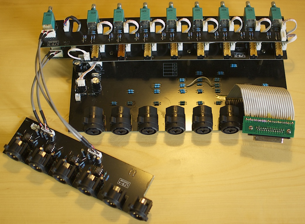
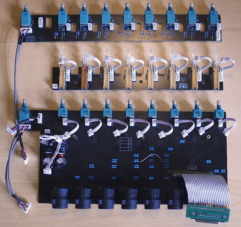
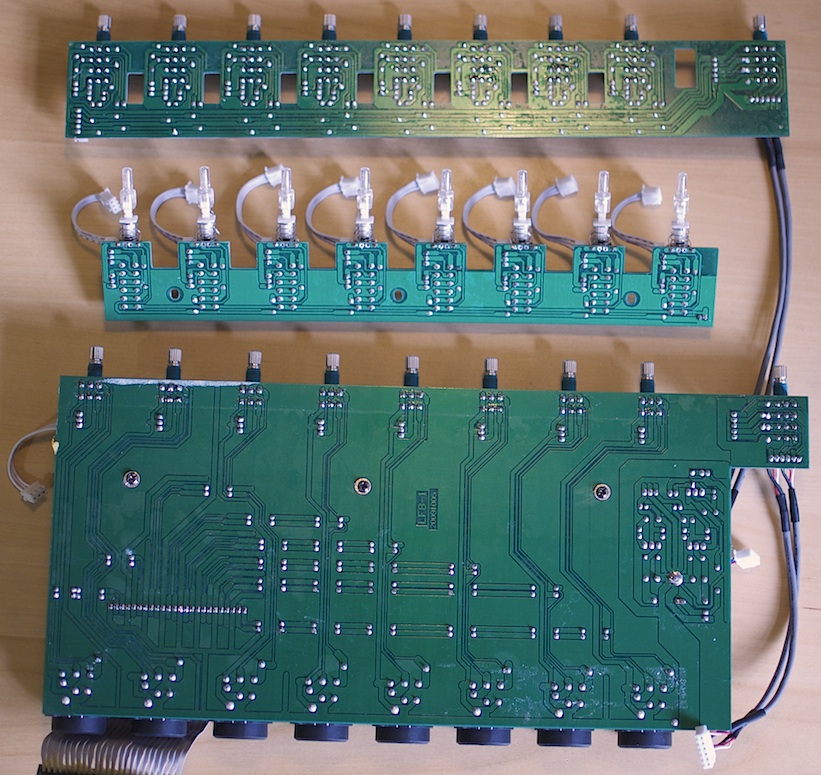
After disassembling it, I have taken a couple of picturs of the interior:

DSC_4180.jpeg


DSC_4184.jpeg


DSC_4185.jpeg


Compared to the older pictures that were posted here, it seems that SM Pro Audio not only changed the apperance, but also the circuit designs. If I am not wrong in the old pictures the circuit looks internally unbalanced (look at the pan pots and the wires going from one PCB to the other, as well as the PCB traces to the passive outputs), while now everything is balanced (4 deck pan pots and so on, see the pictures).

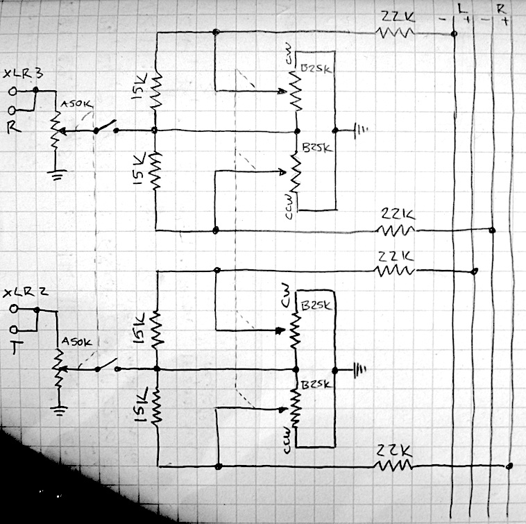
I traced out the circuit and it looks like this (sorry for the hand drawing, it was simply quicker;)):

DSC_4199.jpg


This is pretty much exactly the Forssell schematic (http://www.forsselltech.com/media/attachments/8chsum_1.pdf), down to the resistor values.

Now I have some questions that I hope you experts can help me with:

- Initially, I was thinking of active summing using a Neumann V475 summing amp. However, the resistor values in the existing summing buss are far off the recommended value for the V475. As far as I understand (mostly from your schematics, Dave) the pan pot should have the same value as the summing resistor, so there is no easy way to adapt the resistor values without changing the pan pot. Also all the other resistors involved are probably influencing, too. Is that all true or is there a way to adapt the design to 0-Ohm summing with a V475?
- A different solution would be to use it as passive summing buss and add a line amp card like the V372 as make-up amp. I guess this is feasible. But does it have enough make-up gain? Another thing I am concerned about is the fact that apparently one should not switch channels on an off the summing buss in a passive design. Could this really be a problem? I am thinking of keeping the box always connected to my D/A, inserting outboard in between. So I will not really be disconnecting any channel. Could muting be a problem, or someting else I am not thinking of?
- In general which one of the two ways above would you choose?
- I am thinking of splitting the signal after the summing amp in three paths: main out, monitor out (with additional pad) and headphone amp. Would that be ok, or should I expect some attenuation or other problems?

Please excuse these newbie questions, but I still wasn't able to completely wrap my head around the whole active/passive summing technology...

Thanks in advance,
Mattia
 
One further question:
If I want to add the 4 stereo channels to the summing bus as mentioned above, which value for the summing resistors should I choose for the different configurations?
 

Latest posts

Back
Top