+24V and +48V from one supply

GroupDIY Audio Forum

Help Support GroupDIY Audio Forum:

This site may earn a commission from merchant affiliate links, including eBay, Amazon, and others.

jrmintz

Well-known member
Joined
Jun 4, 2004
Messages
998
Location
NY
Hi all,

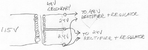
There has been discussion about getting +24 volts and +48 volts from the same supply, and different kinds of voltage doubler circuits to provide the voltages. I was wondering if wiring a 24-0-24 transformer like this would eliminate the need for a voltage doubler, and if there are any particular advantages or disadvantages to doing it this way.

transformer.jpg


Thanks
 
as long as current draw aren't maxed I don't see why not.. I use 120v trafos with 50v taps for various things here at work with no problems.
 
[quote author="jrmintz"]I was wondering if wiring a 24-0-24 transformer like this would eliminate the need for a voltage doubler, and if there are any particular advantages or disadvantages to doing it this way.[/quote] Seth, I believe you can actually use two sets of rectifiers and put the two outputs in "series" for 48V and in "parallel" for 24V but with twice the current capacity for the config that you've shown. That way the load is spread evenly on the two secondaries.

I'll think about this and draw it out and then email that to you. But PRR will quickly be along to beat me to the punch, I'm sure.

HTH!
Charlie
 
Seth,

I don't think you can't use that setup - at least not with two bridge rectifiers, if they both have to refer to the same ground in the end.

Charlie's idea is better - build a standard +/-24V supply with just one bridge, and use the -24 as "ground". Then you have +24 and +48 in a simple way.

Jakob E.
 
You can wire the secondaries in series, get 48VAC, rectify, filter, regulate to 48Volts DC. Then tap from the regulated outputs and further regulate to 24VDC with another regulator.


XFRMR --> 48VAC rectify -- regulate to 48VDC --+-- regulate 24VDC ---+
 
Good idea, that's why I need a 24 AC!!! adaptor.
going into my rack (safety) and make a pcb inside for the regulation.
Very hard to find here in Europe.
Farnell no, RS no :cry:
anyone ?
 
Thinking of it as a dual 24V supply is probably the easiest way to go. I'm sure you can use something like Keiths PSU supply but with 24V regulators, and simply ignore the phantom supply on his board. Presumably the 'top' supply that gives you the 48V (phantom) will not provide as much current as the 'bottom' supply, so you can use a smaller resevoir cap on that. Just be careful that you are not shorting something out by mistakenly connecting a power-rail to ground! Some extra filtering from +48 to ground is probably a good idea, too.

Starting with the +48 and then regulating down to +24 will be a bit of a bitch...I don't think many regulators like to see such a large difference between input and output, and you'll probably need to drop most of that difference in another way if planning on using common regulators.

Bjorn
 
Thanks everyone,

I've been using Keith's supply and it works great. I just looked at a transformer today and this question popped into my head. There's more than one way to get from point A to point B.


:guinness: :guinness:
 
Man, you guys are cheap!
Just buy another x-former for crying oit loud!
Oh wait, I am spoiled in iron, so maybe I am biased.
I am thinking 48 volt battery for ultra low noise.
Would power half the mics in the US!
Trickle charge during off hours.
Be careful! Massive dc if a short occurs, then the house burns down, along with all your prized diy!
Fuses everywhere.
:razz:
 
[quote author="andre tchmil"]Good idea, that's why I need a 24 AC!!! adaptor.
going into my rack (safety) and make a pcb inside for the regulation.
Very hard to find here in Europe.
Farnell no, RS no :cry:
anyone ?[/quote]

how about getting a 24VAC transformer, and putting it in a small enclosure? this way you can run a standard plug to the wall/powerstrip without eating up precious socket real estate. probably wouldn't cost TOO much more...
 
How about something like this... the outputs are actually more like 56v and 28v, which would be just right for driving the regulators.

power.gif


regards, Jack
 
Stop showing off CJ!

Jack,

As shown, you're basically sticking 48V ripple on top of your 24V ripple, making even more ripple! Why not stick the top half on a regulated 24V instead? Basically, two independent 24V supplies one on top of the other will work just fine...as long as they are both floating you can think of them as batteries. They don't really care what you connect to what, they'll just try to make sure they've got 24V between their terminals!

Bjorn
 
Be careful when you stack stuff, since metal that is used to being grounded, ie, cap cases, is now sitting at 24 volts. Troubleshooting reqires extra care in that case. One slip of the voltmeter probe and k-blloooooy Louie!
I think what we need is a transformer speced out at 24 vac and maybe 38 vac. I will hunt around.
 
Why do you not want a voltage doubler? Nothing wrong with that. You don't need a center-tapped transformer, either. Just make it like the positive side of this: http://www.forsselltech.com/gerbers/MikePrePS1.PDF . If it's good enough for Fred...
 
I sent a sketch in pdf to Jakob earlier to post. I don't have a way to post/host.

If you tie the two center wires together as a center tap as shown in the first drawing, then use a full wave bridge across the highest and lowest wires...the bottom wire is now gnd. The center tap becomes +24V. Its hard to describe but the pic explains it all.

You only need 4 diodes to accomplish it and it spreads the load evenly across the secondaries. This was drawn by the Sr. designer at my day job after I mentioned it in passing. He is smart.

Peace!
Charlie
 
you're basically sticking 48V ripple on top of your 24V ripple,
hmmm, I did a simulation of the supply and could not see that effect... but we know how simulations are. Nevertheless, the 48v power requirements will be light and the regulator can easily handle it. You probably would use an additional capacitor in front of each regulator as per the app notes.

Stacked capacitors are quite common in guitar amp power supplies where there are hundreds of volts involved...

regards, Jack
 
thats right, twin reverb stacks them

I don't know if it's a good idea to power an amplifier and phantom from the same transformer winding. Any fluctuations ijn supply voltage caused by the amp will show up in your phantom supply, unless you regulate the heck out of it. I mean, if you want minus 198 db crosstalk, this is not the way to go!
I have never seen a commercial product that does not use at least a seperate winding to make phantom power.
 
Hi Jack!

330 am in London so this is definately my last post tonght!

Try that simulation without the caps, or with them vastly reduced, and make sure there is a good load. I'm crap with simulators, so I don't know how well they work.

If you think caps in series, the top rail only has 500uF, whilst the middle rail has 1000uF. For high volts and guitar amps, 'series stacking' is done because one cap can't take the voltage on its own, and they usually have equal high value resistors in parallel too to ensure that they 'share' the voltage equally.

See you tomorrow,

Bjorn
 
Why do you not want a voltage doubler?

Tim, it isn't that. Some of my best friends are voltage doublers. :green: I've just tripped over some of these issues in a project and I really want to understand the relative merits or problems with the different ways of powering things. I see there are real problems with trying to rig up a transformer to do different voltages, although Charlie's way makes a lot of sense.

Thanks, guys
 

Latest posts

Back
Top