SSL comp question to Jakob

GroupDIY Audio Forum

Help Support GroupDIY Audio Forum:

This site may earn a commission from merchant affiliate links, including eBay, Amazon, and others.

chrissugar

Well-known member
Joined
Jun 4, 2004
Messages
1,315
Location
EU
This is the first time I'm looking seriously at the SSL clone and after studying most of the documents [schematics, PCB, comp lists] I think I discovered some errors.
In the parts list there are mentioned 25 100nF and 9 100pF capacitors. I looked at the schem and the PCB and I think something is wrong. On the PCB where is tha 202 VCA emulation circuit there is a capacitor between the 5534 and the 21XX circuit. It is in paralel with the 1K feedback resistor for the 5534. In the schem the value is 100pF, and for me it seems normal but if you use this value you need 12 100pF and only 23 100nF. If it is 100nF then I think it is because it works only as a DC amp for control voltage ??? Which is the right value?
Another thing is that on the schematic there are two 100nF in paralel with the 1000micro PSU caps, but on the PCB they are not. They are after the 10ohm resistors, at the inputs of the 78L12 and 79L12.
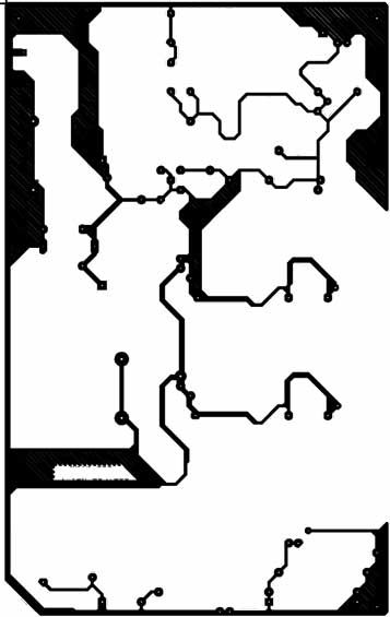
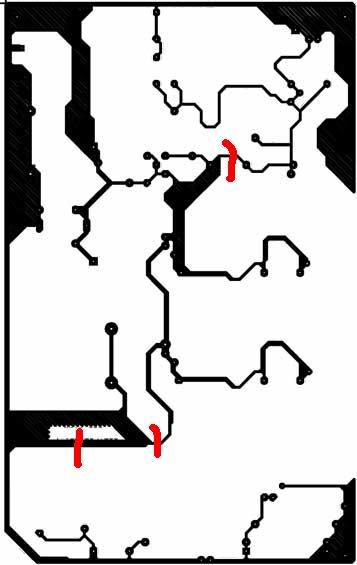
Also I found two ground loops on the PCB. This is not a big problem because we can cut the trace but it would be better to make the mods in a new PCB revision.
Thank you.

chrissugar
 
here's the groundconnection from the pcb...

sslground.jpg


find the loops!

adios,
corneel
 
OK, here goes my try

sslground_mytry.jpg


I just cutted the loops without any analyses of the board. I bet with a little thinking, better points could be found, but maybe cutting any point just to break the loops is what it takes to get the hum down...
 
that's ok, if it makes you feel better, I have two boards, fully stuffed and soldered. :grin: I'm 4 1.2M resistors away from being done ( other than testing, of course)

No worries. Many people have built this project and said they like the sound, plus the ground loops are easy to fix with a dremel tool w/cutoff wheel.

ju
 
I'm well aware of the circulate grounds present in the SSL layout - but I made several different versions (I think 11 or 12) before posting the diy-version, and this PCB actually works much better than any of the others I tried.

We are very dependent on stable reference distribution on this one - the VCA's use very low-level DC control voltages - and these things are easy to upset.

Also, there has been absolutely NO ground-related hum problems in any of the 'clones I ever made. If you have hum, I think it's safe to say that you can rule out the pcb layout.

If you change the PCB layout, you should be prepared to fix a whole lot of instability issues. I wouldn't recommend that - this is a proven design as it is.

The feedback cap in the emulation circuit is an experiment. It started out as a 100p stabilisation cap (at rather high frequency, admitted), but the 100nF with it's slight integration turned out to make the circuit work in a (subjectively) nicer way. Yes, you could argue that this wouldn't affect the "real" 202 if you use that one, but these will behave a bit different anyway.

Don't worry too much about the number of 100nF psu stabilisation caps - I just shove them in wherever fast opamp operation is expected, or where regulation is important.

The PCB has changed several generations since the schematic was updated - that's why there is these slight differences.

:grin:

Jakob E.
 
Thank you Jakob

Untill now I was involved in other projects so the SSL comp was not on my priority list but recently I decided to build it, so before anything I examined all the documents related to the subject to avoid later problems.
Sorry, I had no intention to criticise your work, just discovered some things and needed some confirmation. I suposed there is no serious problem as long as many members managed to build it without problems.
About the 100nF feedback cap, that was what I thought that it should work anyway and the higher value is ok because it is for DC control.

I supose if the transformer is not on the board, at a reasonable distance and the case is shielded there is no humm problem, so my question was more like "anyone had problems with the ground loops"

Thank you for the clarification.

chrissugar
 
just a side note,
mine had the onboard transformer and even in unbalanced working conditions it's dead quite, no hum.. ZERO!
:thumb:
 
What can be worst than a power transformer close to an audio circuit. It can't be closer than that. :grin:

chrissugar
 
Back
Top