the Poor Man 660 support thread

GroupDIY Audio Forum

Help Support GroupDIY Audio Forum:

This site may earn a commission from merchant affiliate links, including eBay, Amazon, and others.
khstudio said:
I too am more interested in the "Trimmer" settings... I seriously doubt that "One setting fits all"
This will become more apparent when more builders fill out the "voltage charts" & follow the test procedure for the Control Voltage & post those as well. I've already noticed, from the few already posted, that those control voltages don't exactly match or track the same for each channel... what role does the "Trimmers" have to play in this???
So trimmers settings (sorry I don't have the schematic with me so I won't give the proper RVsomething):
The first one (driving the transistor) is setting the cathode bias.
The second one (in the TC network) is setting the grid bias.
Why did Analag implement 2 bias setting in his comp. I would bet that the answer is :
- You can have 2 channels with quite well matched tubes on each of them but with a difference in their overall gain. It can be solved by changing the Grid bias but the problem will appear again in stereo mode. The cathode bias can solve this point. This is a clever idea of the designer if my suggestions are good.
Hope it help people to understand better those settings. The standard settings are working fine on mine, I haven't got matched tubes ( if they are it's just because I'm maybe lucky ), and I don't have any gain difference between the two channels.

I have distortion when I push my soundcard (TC Konnect8) to the maximum level with no compression. I never managed to have 20dB gain reduction with this card ( not a big deal as I compressed enough for me ).
 
idylldon said:
Nele said:
you did mount all the heatsinks isolated?

something which nearly drove me insane once..

Other than for safety reasons, why?  The heatsinks aren't grounded.

Cheers,
--
Don
HT transistors must be mounted isolated from their heatsinks because they are really close and a contact between them will do some sparks...
 
OK... ready for this one?  ;D

I spent a lot more time today troubleshooting & talking with Doug on the phone.
#1
Doug asked me to unplug everything from the power trans to see if it got hot & check the voltages.
Then, if it passed that test, plug in the PS PCB ONLY to the Power TX!

BOTH of these test passed... NO Heat, Voltages perfect!

#2
Once again I rechecked all connections, removed BOTH PCB's & ohm'd out everything & could not find any problems.
But I'm still getting fluctuation with the Cathode Voltage @ R10, 330r, CH1 PCB - when I switch thru the threshold.
I tried all 4 of my built attenuators & they all do the same thing to that channel!
(CH2 stays steady at around 12v when I move the threshold + my Gain switches work fine too... so I'm ruling out the threshold controls)

#3
Just before crashing out, I decided to try something.
I have just 1 channel connected. (ch1 - the one acting up)
No input gain, Meter or attack MOLEX connectors connected. All others connected.

I was nervous but decided to Plug in just ONE output tube at a time = 5687. (I did have the 2 6BC8's in)
This works & keeps the output balanced - see schematic.

Anyway... when I did this, the Cathode Voltage @ R10, 330r finally stayed consistent when I switched thru the threshold!  ;D :-\
Hmmm... so I then moved the tube to the other socket, Same thing.
Then I tried different tubes... same thing, Voltage stayed at around 12v @ R10.

I then tried putting BOTH tubes back in & WHAM... No good... voltages move around with the threshold again.

What the _____  ???

Bad tube socket?   Maybe ...but how could they be bad when they work individually.
There's only a few component in that section & they all measure good.

any ideas?
 
emrr said:
[silent:arts] said:
it should have been mentioned it is not a beginners project.

It was, I believe.
glad to hear :)

Doug,
even I still think my english skills aren't good enough I feel I have to respond ...
and don't get me wrong :)

emrr said:
it is getting scary.
won't do this anymore.

I'm not sure what's scary to you.  I simply suggest that as a matter of PR, the lack of input or commentary from the designer appears to be both frustrating and scary to many who wish to believe the project is both good and worth finishing.  Many have clearly finished it to success, and moved on.   Others clearly feel the baby has been left in a basket on the steps of the church, without even a note pinned to it's blanket.   I think it's correct to say we've experienced that range of emotion, right or wrong, in this thread. It's disheartening to watch, as a bystander, and I suggest the effects worth observing, as anyone offering a project of any type will find their reputation affected by the public reaction to the follow-through aspect.   A simple observation.

scary to me is:
- one builder having problems spaming the hole thread with 58 posts in 9 days. I called it impatience before.
- claiming why nobody wants to help (with you, lolo-m and moby and some others by side trying to help. thank you all btw)
- claiming missing documentation. this builder has more documentation than any other.

it was never promoted the designer will give support.

emrr said:
at the end, you don't buy support with PCBs.
Volker

Sure, but a private party like this has to have more internal support, to cover that support which is lost with an open-source project that all can view freely.    It took extra requests to get the +/- 17V supply schematic published; to simply state that the +/-17 section is 'standard circuitry' assumes that all builders are well versed in all types of PSU's, which is at best wishful thinking.  It took extra requests to get any detail whatsoever on the setting of the trimmers.  I don't recall seeing any descriptive about what variance in the trimmers might do, and that would seem to be another piece of useful knowledge, especially in a troubleshooting situation.  These are extremely basic support issues, and I would think the effort put into extra support documentation would be worth it, if only to shut down the endless related questions that we experience now.

the "private party" has been a wish of this community to release this project.
if somebody can't see from the PCB how the +/-17V PSU works I don't think he should build it.
since I'm not the "master" of this project I asked first if it is ok to release it, I have to wait for approval. again, somebody might be busy, on holiday, whatever. it might take some time.

my prototype was build without any trimmer statements, voltages. mhm, I didn't touched them and it worked, I played around with them it worked better. isn't this DIY ???
we talked the designer to publish his settings, and he did.

emrr said:
Please know that I only wish this commentary to help; I have no desire to lay out pointless criticism, and wouldn't waste my time on it if I thought it were so.  I am a vested player in this project, only moving too slowly to be much help in troubleshooting at this date.

be sure I'm aware of this, and I thank you for all the support you already did.

I will for sure think over it and how to do the next projects.
if you can't live without analag = no D-AEQ from me.
if you can't live without kubi = no Jensamp from me.
others.
all might be busy with other things in their life.

most sad thing is there are other, more patient builders with problems too.
they have to get support too, and I will concentrate more on this in the future.

by reading this whole thread one offer:
if this specific builder wants his money for the PCBs back I'm open to this option.
I even would buy this complete build (excluding the PSU transformer, this one was never recommended) - just of curiosity what was done wrong with this build.
 
Well stated, Volker.  I would have never thought it was a bad T4!

I suppose my points about documentation and commentary from the designer boil down to one thought: I would think he might feel vested interest in being sure his creation is built and set up properly, and units perform as well as they can be, through correct alignment. 

I'm a little mystified about that point, but he clearly thinks differently.  He's always appeared a great fan of entropy, which on the one hand, might be the very reason I would choose not to release and support a project.  At least not without a good bit of commentary about the 'why's' and 'why nots'. 

Not to focus too much on the trimmers, but they are a good example.  With the trimmers, the options might be:
  • adjust them in this manner for intended operation
  • play with these until you think it sounds right; we don't want to tell you how because we are curious what you like
  • we don't care what you do with them
  • f$&% it, it doesn't matter, just stick in this resistor value instead

It's just strange that there was no comment on them at all, other than '5K or 2.5K will both work'.  Possibly they were leftover from the prototype, and left in the design unintentionally, and could have been converted to a fixed value.  I dunno, I ain't played with it. 

Just as reality check, I don't easily see how much of anything works from looking at a PCB, and I worked in a repair shop for awhile.  I think I have an advantage over the average builder here.  Maybe I was no good at it, I can't really say; things left there working.  By your criteria, I may be unqualified to build the project.  Maybe the key word is 'easily'.  What does that mean?  It is a sincere question worth pondering.  A schematic with a PCB seems a basic roadmap. 

This is sort of DIY.  It's sort of Lego's, too.  Some builders are simple Lego technicians, some are electronics geniuses, most are somewhere in between.  Lego always put together the best manuals on the planet, at least in the 1970's.  ;D  If they made the manuals for everything, the world would be a better place.  Collins Radio may have made the second best manuals, in that they almost always gave a written description of basic circuit function and operation.  It never has to be long, just to the point.

I can't really address others impatience, or lack thereof, not being in their shoes.

I think I've done what I can to address the theory of DIY project offerings, and will attempt to restrict commentary to specific assistance, as was intended by the thread.  I'm overreaching in the first place, having not finished my own build. 
 
i'm not building a 660 and i dont plan to....but i've been following the thread.

However it think every project needs patience...some times we get impatient and we tend to make more mistakes...
So in my opinion you need to go out and take an ice cream Kevin!!! leave it alone for some time and you;ll see clealy afterwards...

I'm telling you that cuz it worked for me while building some gear!

@ Volker you have done a really good job man!

Take care and peace for all........
 
khstudio said:
I decided to Plug in just ONE output tube at a time = 5687.
when I did this, the Cathode Voltage @ R10, 330r finally stayed consistent when I switched thru the threshold!  ;D :-\
Hmmm... so I then moved the tube to the other socket, Same thing.
Then I tried different tubes... same thing, Voltage stayed at around 12v @ R10.
I then tried putting BOTH tubes back in & WHAM... No good... voltages move around with the threshold again.
Bad tube socket?   Maybe ...but how could they be bad when they work individually.

You have a weird interaction there for sure, and who knows if it's the source of all your problems, or one of several.  

It reminds me of an EL34 socket that had some hot glue in it.  The socket had good contact while the amp was cold and during warm-up, but then the glue would melt and flow, and disrupt contact.  Turn it off to troubleshoot, glue re-solidified, problem went away.   Socket replacement was a last resort, and the glue could be seen once the socket was pulled.  

I know you've measured individual socket pins for correct values, continuity, lack of shorts to other pins.  Do it again.  If you can, replace a socket and see if anything changes.  What a PITA.  Then replace the other one if nothing changes.  Look for board faults before and during any socket replacement.  Maybe a junkie at the circuit board factory dropped a used syringe into your circuit board, and it's creating an anomaly.   ;D  

Does B+ voltage stay stable during these moments of cathode fluctuation, or do they bump also?

The weird part is that you have an overheating power transformer, and cathode voltages that go up.  My gut expects to see cathode voltages to go down from interaction.  It sounds like a ground problem, like ground is going high by 50-500 ohms as you switch the threshold control.   How could that be, especially when it doesn't do it with a single tube?   Could be something is making the q4 irf820 give up control in little bursts.  Seems very far fetched.  I see advice now is to use irf840's for both q4/5, so consider that as a dumb thing to try.  
 
On the bright side.. reading this thread makes me want to finish mine! Waiting for the SCAMP-board to arrive and then it's go-time!
I'll do some measuring....

Ice-cream is always a good solution. Any recipes?

 
radiance said:
yes, it's kind of sad... :(  people asking for help in a demanding way.

Actually it makes me sick  :mad:

I assume your talking about me.  ;D

Well, Sorry to everyone who feels that way.
Even though I'm posting a lot, most of my posts are about the testing & readings I'm getting so I can get some helpful feedback.
This was an expensive project not only with money but TIME... for me at least.
I had a week off work to focus on finishing this project & used every waking minute with no resolve.

The only thing I really asked for (not demanded) was a voltage chart (which I made & posted myself & "asked" people to PLEASE fill out) This IS NOT just for me!!!

Don't worry... I don't want my money back.
I will remove ALL my posts & voltage chart & I'll look elsewhere for help if that would make everyone happy.

Thanks to everyone that tried to help me... including Volker, Moby, etc...

PLEASE... Don't confuse my perseverance with impatients!
 
lolo-m said:
Try an exorcist on this board  ;D ;D ;D !

Sorry for the joke, I'm stumped...

;D I laughed at this one because I though the same thing.

One thing I can say is, I learned a lot about "Vari MU Comps" during all this.

I think the only thing left to do is swap out the tube sockets & surrounding resistors ... I did use different sockets for the 5687's & they may be junk.
 
$.02:  Put a quick summary on a post-it, stick it on and lock it in the closet for a few weeks.  Engage your energy in something fun and productive.  Don't even think about logging on here.  Listen to some music that you like :)  This sh!t is not important.  Come back to it when you think it will be fun again.  When you solve the mystery in the right frame of mind you will enjoy it so much more and you can share that success here. Everyone will think your a wizard if it was complicated or have a good laugh if it was a stupid error.  Either way it'll be fun and entertaining.

Best of luck to you.
 
I will remove ALL my posts & voltage chart & I'll look elsewhere for help if that would make everyone happy.
No,no, that will be the waste of energy! i think that we are here to help and understand each other. I don't have a problem because you are posting a lot, I'm sorry because I can't give you voltage chart .Mine PM's are half finished and it worked once (out of box) but I decided to finish it, so now its in a parts again....  :-\


Guys, be more positive and don't give sucha harsh comments.
 
Kevin,
dont pay any attention to those negative posts regarding count of your posts...
let them stay sick  ;D

i wonder, if you had the working V chart...

kam


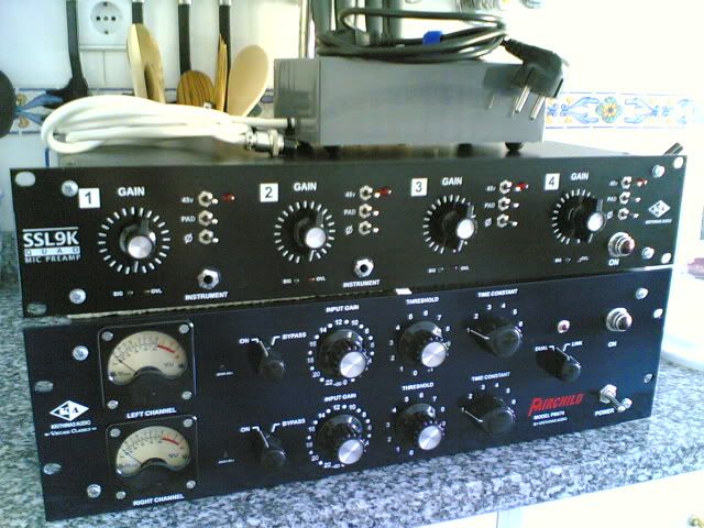
Hello, just post to put a really bad quality photo of my PM670 and my quad SSL9K...
One channel of my PM670 still is not working properly... but here it goes to you...

QUADSSL9K.jpg


Ps.: yeah... is in the kitchen  :p

Cheers friends ;)

Eddie ;D
 
khstudio said:
I will remove ALL my posts & voltage chart & I'll look elsewhere for help if that would make everyone happy.

I wouldn't do that, but in the case of anyone who's posted a lot in series as Kevin has, I might suggest consolidating information as it develops, and editing posts for brevity.  You could do a new run down of the facts and tests, in clear detail, and also may be go back to the previous posts and add something at the top like:

disregard this post, see (link) this summarized update.

Lots of serial posting does get hard to follow, and that would make your problems easier to follow.  I hesitate to suggest outright nuking, as it can make a thread make no sense.    But if you can nuke something without impacting the thread, why not? 

Volker has kept up with adding links to the first post of the thread, and that's the best overall summary we have.  Maybe as specific troubleshooting tips develop, they can be linked there too. 
 

Latest posts

Back
Top