SSL PPM meter

GroupDIY Audio Forum

Help Support GroupDIY Audio Forum:

This site may earn a commission from merchant affiliate links, including eBay, Amazon, and others.

livingnote

Well-known member
Joined
Aug 12, 2007
Messages
1,048
Location
Berlin, Berlin
Hi, I am in the middle of bringing them bargraphs to life, and am trying to get the blue one to act as a ppm meter. So far, I am using a 3916 and the PPM rectifier circuit recommended from National, what I am wondering is this: where is the best point to get an accurate level into the meter so that it's a serious meter and not just a cool string of flashing lights?

Best,

Lukas
 
LM3916 is a linear-scaled bargraph driver, -no?

If so, it's not much suited to audio applications without a log-scaler.

A 3915 (IIRC) is better suited for signal level aplications.

Also, what circuit are you referring to? -9K? GSSL? We'd really have to know in order to answer.

Keith
 
[quote author="SSLtech"]LM3916 is a linear-scaled bargraph driver, -no?[/quote]

No.
"The LM3916 by itself covers the 23 dB range of the conventional
VU meter. To display signals of 40 dB or 70 dB
dynamic range, the LM3916 may be cascaded with the 3
dB/step LM3915s" from National datasheet.

Regards,
Milan
 
Yeah, as far as I can tell the 3916 differs from the 15 in that it's "differently logarithmic" to display the db in whole numbers per dot, but how exactly that works ain't my bright side ;)

The 14 is definitely linear, that's the one I'm using as a GR meter.

It's for the GSSL, I previously used 2 3914s with a simple voltage divider to indicate pot status because I like blinky stuff, here's the picture:

bling.jpg


Now I decided to put the front panel board document online so that everyone can etch their own, and of course got to looking at it a little closer, then got to designing and wanted to implement this thing I had lurking in the back of my mind: to put those bargraphs to some practical use. Luckily enough you can perfectly fit your chips right into the front panel pcb (even though I almost went nuts over the control board topology...it's like sudoku from hell).

What I'm wondering is where to get the signal from to drive the PPM meter, so that for one you can get an accurate reading of what your output level is and for an other the meter doesn't in any way influence the signal chain. The two places I was thinking of were either to meter right after the VCAs before the output ops, or after them, maybe just grab the positive out and feed it to the meter. That would make the most sense to me personally, because what you're seeing is what's coming out and you're not anywhere near the VCA, except I don't wanna unintentionally whack the output out of symmetry by tapping just one end, I don't know what a difference this would make.
 
Ah... I had my numbers mixed up. 3914/3915/3916... they're all starting to blur into one!!!


Take your output indication from pin 1 of each of the output 5532's. If you want to take an input indication, you can find one at pin 6 of each of the two input 5534's.

Keith
 
[quote author="livingnote"]I like blinky stuff[/quote]

What about using LM391x and a stereo pot for threshold, makup. You can use the free pot 'layer' to give a control voltage to the LM391x. This would make a kind of rotary encoder. Could look interesting with plane surface leds or acryl around the pot. Doesn't make much sense but its blinky, too. :green: Or gain reduction leds around threshold and output volume leds around the make up gain pot. :cool:
 
http://en.wikipedia.org/wiki/Peak_programme_meter

I just love the Internet,,, learned something new today.. I thought PPM was a single coherent standard (4 mSec attack, slow release), but it appears there are several different PPM variants. EBU is 10 mSEC, while there is a Nordic IEC PPM with 5 mSec. One thing I'm also uncertain about, is the time constant is described as reaching 80% of stimulus level, while 80% is more like 1.6 electrical timeconstants.

I used 4 mSec (RxC) on peak meters I did back in the '70s-'80s.

YMMV, to avoid missing sharp transients for modern digital recording you may want to go faster, the slower attack was based on audibility of transient distortion, by us meat puppets.

JR
 
Hey, didn't know that yet either...it does seem like it would be a good idea to make it really fast for digital inputs.

@nrg, well, that's exactly what I'm doing. The implementation on the picture up there is with stereo pots as a passive status indication and I'm working on making them GR and PPM. Board design should be finished sometime this month, then it's off to prototyping and if it all works, upload it goes.

:twisted:

Ah yeah, by the way one of the more practical things about it is that you can save space in the rack case that would otherwise get eaten by ye olde meter, meaning you can stick a nice crush-n-blend in there, plus hipass.
 
Bugger the Hipass...


TURBO IT, BABY!!!

...Of the few hundred that have been sold thus far, the reactions are pretty unequivocal.

I did know about the different scales: The SSL PPMs had to have different scale overlays, and Ernest Turner, Sifam etc all supplied different meter scale plates to meet the various different standards... I seem to remember there being more than a dozen different PPM standards in all...

..In fact last AES, I was handed a VERY tidy-looking pocket cross-reference index card for translating between the various standards, from an electronic meter manufacturer... -wish I could find it now.

The apparently slow attack speed stems from the need to mitigate the accelleration/deceleration requirements for the mass of the meter movement plus the pointer... In electronic display terms of course, there need be no such restriction, but at a certain point, you're long since quicker than the eye can determine.

Keith
 
PPM "attach time" is called integration time. It is the time that is reguired that reading reaches 0,2 Nepers (about 1,7 dB) below steady state reading. Recovery time is usually per 20 dB.
 
Ay cool! I'm gonna turbo it next thing once I get this front plate up and running. I was actually thinking about going for relay-controlled dual mono feature while I'm at it, too...
 
Doable certainly... though rather complex. -You would then need two sets of attack, release, threshold, ratio, makeup and relays to switch to a common set of controls when in stereo mode(s).

...Oh, and two GR meters, of course...

-Rather easier to built two separate one-channel-loaded-only mono GSSLs, then use relays to combine/re-separate the CV/sidechain stuff as per the "ultimate" GSSL thread.

-Not impossible, but certainly not for the faint of heart!

Keith
 
I was thinking of doing just that, with the one-channel-loaded-only SSL fully loaded but with your cool polarity-flipped implementation...Aarhus, Oxford, Dual Mono, Ext. SC In, crush-n-blend, GR, PPM...scrumptious :)

I got the tip for Takamisawa being good relays to build into the box...
 
From the link I provided, the early BBC peak meters were capable of 1 mSec attack times, but they intentionally slowed them down 5 to 10 times that to account for the low audibility of very brief transient overload.

JR
 
YEAAH! It Works!

A bit of getting up to speed on what's been going on:

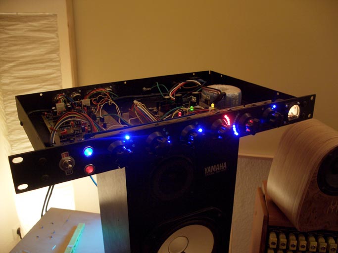
Implementing the PPM meter led me to redesigning the entire control board so that I could fit everything on it. Main reason for this was that I needed the bypass on the right to be on the same board in order to make sure all the LEDs have their little heads popping through the front panel. You need pressure from both sides to get it right (the one in the picture above was stitched together).

There are a few things I learned while I was at it. First and foremost, selection of chips:

3914 : linear
3915 : -3dB steps
3916 : -20, -10, -7, -5, -3, -1, 0, 1, 2, 3dB (which is the VU scale).

They don't SAY this in the datasheet.

This led to some major aarrgh because I wouldn't have known a VU scale if it had hit me over the head. I called up Nat Sem and the guy told me "well, that's a very old part, the guy who designed it is no longer on this earth".

very reassuring :?

Anyway, the main reason I called them is that I tried setting Vref (btw do americans really use the index V for voltage as opposed to U in Germany?) and it turns out that as long as you want your top LED to light at +4dBu, you're ok (well, sort of...). But if you want, for example, to work to -6 dBu into your DAC you can forget the internal reference. It doesn't go below 1.2V, and any attempt to calculate a divider below that leads to such adventurous resistances as "-380Ω".

So, all the internal ref was good for was for setting LED brightness (resistor off Rout around 1.2k does the job well) and short Radj to GND.

So you need to build two precision dividers (as in "Vishay" and "64") in order to set an external ref window that keeps with the dynamic range of your IC. Simply using one for refHi and shorting RefLo to GND does NOT do the trick because your 3dB increment goes to gehenna.

Stable 12.28mV DC source, anyone?


But like all these stories it worked out just fine, and I learned a lot about dB along the way. An interesting question would be: What would you like your little meter to indicate: straight dB steps or something more VU-esque? I can imagine that for things like Classical, you're better off with 3dB steps, as they have a wide dynamic range, for rock n' shit you might go for the VU because with all that compression, being able to read out 6 dB over 5 LEDs is a real advantage. As Bungie once said, "youth is only satisfied with major damage and total carnage" :twisted:

That you can change that by poppin' chips is just awesome. LM39xx designer, wherever you are, here's to you :sam:

I'll be posting some pictures later :grin:


edit: The 3916 is a lot more fun! For most music, all you'll get out of that 15 is some 3-LED action...
 
u and V and not German or American. V is a Voltage ratio reference but generally 1V is implied for "0 dBV". 0 dBu is again a voltage reference but to .775V which just happens to be the voltage at a 600 ohm termination that generates 1 mW.. The actual standard is 0 dBm = 1 mW. I have also seen small v used interchangeably with u but AFAIK it isn't widely accepted.

I used a 3915 to make a simultaneous Peak VU meter, by displaying the peak in dot mode and VU in bar mode.. I used a 4016 cmos gate to toggle the 3915 back and forth fast enough to fool the eye into thinking the display was constant.

JR
 
> do americans really use the index V for voltage as opposed to U in Germany?

V for Voltage. Where do you guys get "U"?

> But if you want ... to work to -6 dBu... forget the internal reference. It doesn't go below 1.2V, and any attempt to calculate a divider below that leads to such adventurous resistances as "-380".

There WAS an extensive Application Note/Brief on the LM391x series, but NatSemi does not seem to have it listed.

If you want a 0.61V reference, set Vref to 1.23V, use external divider to cut that in half, and apply to the Rhi pin. If you want a 0.1V full-scale reference, you will run into trouble with the many-milliVolt errors of the comparators, your lowest bits will be way off the mark. Duh! Run your 0.1V signal through a X12 amplifier. National makes opamp chips and is happy to sell them.

I once did a major screw-up, had a 14V-15.2V span and the '3915 "had" to be sitting on ground. Differential amplifier to subtract the 14V and get it into the 3915.

> the VU scale.
They don't SAY this in the datasheet.


http://www.national.com/mpf/LM/LM3916.html#General%20Description
"The LM3916 is a monolithic integrated circuit that ... provid{es} an electronic version of the popular VU meter."

Seems to me, if it is a VU meter chip, it will be VU meter markings. -20, -10, some 1dB steps around zero VU, and a few more to bridge the long gap between low and normal.

I've used a lot of these. But what is really interesting: almost NO commercial product does. Nearly everyone rolls their own from a box of LM339 chips and a resistor assortment. 10 LEDs is not enough for some things, too many for others, LM391x is very nearly single-source and still costs a dollar, while '339 is cloned everywhere at $0.20.
 
[quote author="PRR"]

V for Voltage. Where do you guys get "U"?
[/quote]

It comes from the latin word "urgere" which stands for "push, float"..
(my source is German Wikipedia :wink:)
 
[quote author="livingnote"]3914 : linear
3915 : -3dB steps
3916 : -20, -10, -7, -5, -3, -1, 0, 1, 2, 3dB (which is the VU scale).

They don't SAY this in the datasheet.[/quote]
That's not fair to that old dead designer or the datasheetwriter, the three datasheets each do say the stuff above.

(btw do americans really use the index V for voltage as opposed to U in Germany?)
I'd say that's turning the world upside down :wink:
As I understand it 'U' is only used in or near Germany and the rest of the world does 'V'. We also use V here in NL.

Enjoy the LEDs,

Peter
 
Back
Top