


Hi people!
Let me introduce new funny and great sounding project-
WIREGAIN-DC
It is digitally controlled PGA-2500 based pre-amplifier,
very clean sounding, with excellent transient response, ultimately low noise, etc...
WIREGAIN-DC can be compared by specs and sound-wise to top range
clean commercial stuff in k$ range.
Gain: 0...75 dB, in 1 dB steps, controlled by rotary encoder and displayed on
2-digits 7-segment display or....IN-12 Nixie tubes in other test version.
-20 dB pad automatically inserted at 0...19 dB, and switched off at 20...75 db.
No clicks, no pops.
As pure benefit of digital control, PHANTOM switch is smart as well.
When pressing 48V button, pre's gain set to minimum, then phantom relay goes on,
then gain softly set back to original value with speed of 5dB/sec.
120 Hz High Pass Filter placed at the input of preamplifier.
PGA2500 has constant input impedance, and great feature - common mode servo.
It allows to use simple passive filter. With a little trick, no clicks or pops as well.
BTW, most pre's using filter after gain stage...and I can't see any reason why to
amplify all this rumble-mummble then cut with active filter.
Next feature is kinda limiter, we called it OVRP.
When OVR button is pressed, controller watching OVR signal coming from PGA2500.
If maximum level less 3dB reached, signal OVR changes from 0 to 1.
It used to take gain down. When OVR disappears, gain returned back.
Gain structure: input circuit-phantom-pad-HPF-PGA2500-balanced output stage (+10dB).
Pre-amp runs on +/-22v if NE5532 used at the output or +/-24V in case of OPA2604.
Power supply has +5v used for relays and +48V for phantom.
Maximum output level of WIREGAIN-DC about +26dBM.
It is unbalanced-compatible, i.e. when pin 3 of XLR shorted to ground, by changed feedback
"minus" don't care, and "plus" signal jumped up by 6dB remaining gain same
as in common line drivers like SSM2142, DRV134, THAT1606.
Schematics:
http://i251.photobucket.com/albums/gg291/diy33609/pga2500/contr_schem.gif
http://i251.photobucket.com/albums/gg291/diy33609/pga2500/pre_schem.gif
(please note, some errors can appear beacause all you see on pictures
is preliminary version of full system's pcbs adapted for single pre-single controll purpose)
More images and video:
http://i251.photobucket.com/albums/gg291/diy33609/pga2500/P1010370.jpg
http://i251.photobucket.com/albums/gg291/diy33609/pga2500/P1010372.jpg
http://i251.photobucket.com/albums/gg291/diy33609/pga2500/P1010374.jpg
http://i251.photobucket.com/albums/gg291/diy33609/pga2500/P1010376.jpg
http://i251.photobucket.com/albums/gg291/diy33609/pga2500/P1010368.jpg
http://i251.photobucket.com/albums/gg291/diy33609/pga2500/P1010379.jpg
http://i251.photobucket.com/albums/gg291/diy33609/pga2500/P1010381.jpg
http://i251.photobucket.com/albums/gg291/diy33609/pga2500/P1010382.jpg
http://i251.photobucket.com/albums/gg291/diy33609/pga2500/P1010383.jpg
http://i251.photobucket.com/albums/gg291/diy33609/pga2500/P1010394.jpg
http://i251.photobucket.com/albums/gg291/diy33609/in12.jpg
http://i251.photobucket.com/albums/gg291/diy33609/plasma2.jpg
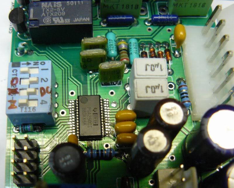
Only 4 chips used in this pre-amp: PGA2500, OPA2604 (or NE5532),
microcontroller and BCD-to-7-segment decoder.
Project is really simple at all. One only hard thing- is soldering the PGA2500 on pcb...
with some patience, and Legendary Pink Dots playing from LP on background, possible.
I checking the option to make this project DIY, and in case at least 50 pcb's
will be ordered, you will find it in my sticky list of projects at this year.
Price of PCB's and controller chip will be about EUR40-45 include shiping, with qty discount.
Are there people interested?
Let me introduce new funny and great sounding project-
WIREGAIN-DC
It is digitally controlled PGA-2500 based pre-amplifier,
very clean sounding, with excellent transient response, ultimately low noise, etc...
WIREGAIN-DC can be compared by specs and sound-wise to top range
clean commercial stuff in k$ range.
Gain: 0...75 dB, in 1 dB steps, controlled by rotary encoder and displayed on
2-digits 7-segment display or....IN-12 Nixie tubes in other test version.
-20 dB pad automatically inserted at 0...19 dB, and switched off at 20...75 db.
No clicks, no pops.
As pure benefit of digital control, PHANTOM switch is smart as well.
When pressing 48V button, pre's gain set to minimum, then phantom relay goes on,
then gain softly set back to original value with speed of 5dB/sec.
120 Hz High Pass Filter placed at the input of preamplifier.
PGA2500 has constant input impedance, and great feature - common mode servo.
It allows to use simple passive filter. With a little trick, no clicks or pops as well.
BTW, most pre's using filter after gain stage...and I can't see any reason why to
amplify all this rumble-mummble then cut with active filter.
Next feature is kinda limiter, we called it OVRP.
When OVR button is pressed, controller watching OVR signal coming from PGA2500.
If maximum level less 3dB reached, signal OVR changes from 0 to 1.
It used to take gain down. When OVR disappears, gain returned back.
Gain structure: input circuit-phantom-pad-HPF-PGA2500-balanced output stage (+10dB).
Pre-amp runs on +/-22v if NE5532 used at the output or +/-24V in case of OPA2604.
Power supply has +5v used for relays and +48V for phantom.
Maximum output level of WIREGAIN-DC about +26dBM.
It is unbalanced-compatible, i.e. when pin 3 of XLR shorted to ground, by changed feedback
"minus" don't care, and "plus" signal jumped up by 6dB remaining gain same
as in common line drivers like SSM2142, DRV134, THAT1606.
Schematics:
http://i251.photobucket.com/albums/gg291/diy33609/pga2500/contr_schem.gif
http://i251.photobucket.com/albums/gg291/diy33609/pga2500/pre_schem.gif
(please note, some errors can appear beacause all you see on pictures
is preliminary version of full system's pcbs adapted for single pre-single controll purpose)
More images and video:
http://i251.photobucket.com/albums/gg291/diy33609/pga2500/P1010370.jpg
http://i251.photobucket.com/albums/gg291/diy33609/pga2500/P1010372.jpg
http://i251.photobucket.com/albums/gg291/diy33609/pga2500/P1010374.jpg
http://i251.photobucket.com/albums/gg291/diy33609/pga2500/P1010376.jpg
http://i251.photobucket.com/albums/gg291/diy33609/pga2500/P1010368.jpg
http://i251.photobucket.com/albums/gg291/diy33609/pga2500/P1010379.jpg
http://i251.photobucket.com/albums/gg291/diy33609/pga2500/P1010381.jpg
http://i251.photobucket.com/albums/gg291/diy33609/pga2500/P1010382.jpg
http://i251.photobucket.com/albums/gg291/diy33609/pga2500/P1010383.jpg
http://i251.photobucket.com/albums/gg291/diy33609/pga2500/P1010394.jpg
http://i251.photobucket.com/albums/gg291/diy33609/in12.jpg
http://i251.photobucket.com/albums/gg291/diy33609/plasma2.jpg
Only 4 chips used in this pre-amp: PGA2500, OPA2604 (or NE5532),
microcontroller and BCD-to-7-segment decoder.
Project is really simple at all. One only hard thing- is soldering the PGA2500 on pcb...
with some patience, and Legendary Pink Dots playing from LP on background, possible.
I checking the option to make this project DIY, and in case at least 50 pcb's
will be ordered, you will find it in my sticky list of projects at this year.
Price of PCB's and controller chip will be about EUR40-45 include shiping, with qty discount.
Are there people interested?
")