Winding an output transformer...

GroupDIY Audio Forum

Help Support GroupDIY Audio Forum:

This site may earn a commission from merchant affiliate links, including eBay, Amazon, and others.

lolo-m

Well-known member
Joined
Dec 14, 2005
Messages
759
Location
Avignon, France
I bought a C-core kit to make an output transformer...

Must I wind the primary on one bobin, and the secondary on the other, or is it better to wind both on both bobins ?

I'm quite sure it's better to wind on both and if it is, primaries closer to iron or secondaries ?

The primary inductance must be high... I was thinking to get the "classic" inductance of a power transformer (about 50H ). Is the inductance law the same on a C-core transformer than on a ferrite based inductor ?
 
You would probably want to make some interleavings to minimise the leakage inductance, for example here's a 5-layer version:
traf3.gif


traf4.gif


the writting under the last picture sais to wind all layers in one direction. Don't know how it looks exactly on a C core but you get the idea.

I just found that page:
http://www.audiohobbyist.com/projects/diyopt.htm
it seems he interleaves in a similar way.

Let me check if my handbooks say anything about winding on C cores. I'll be home in a few hours.
 
Thanks for these infos michal_k :) :) :)... They're answering to some of my questions.
I've read somewhere that copper shield interleaving changes something else than capacitance too. I can't remember if it is inductance or ratio... maybe both  ;D... As it isn't an input transfo, shielding isn't necessary, what about paper or mylar interleaving ? Do someone know if I can use those electrostatic food platic films to do it ? or electric gaffer tape ? (I don't really know where I can find mylar nor wax paper).
 
For true vintage look I'd use that thin greaseproof paper. I remember reading about it somewhere. It's good to insulate every layer of winding with paper treat it with shelack*.

Unless you have some prespan paper of course, but I don't think it's still aviable nowadays.

Checked the book I mentioned before. No drawings, a lot of text in polish. Unfortunately I don't have enough time to translate it right now.

*is it output trafo for a tube amp?
 
Create a folder in your Program Files called "OPT_da"
Then

Go to this link:  http://www.dissident-audio.com/OPT_da/Page.html
Click on the blue box with " Download" on it.
Then unzip to your new folder.

Have fun!

14tc4r6.jpg
 
On a C-core you want to wind identical bobbins and connect them accordingly. For best result have an inductance meter nearby. Also the inductance rises as you clamp the core tighter, so have a good frame to hold things together. If you must interleave, you can wind (3) primary sections and (2) secondary sections per bobbin. Parallel connect all your secondaries so the you can use smaller wire for a neater wind (if you choose). Personally I like to make a former (side-less bobbin) and wind layer by layer and apply varnish as  I go. If this transformer will be handling B+ like a tube amp output you will want to use something like polyester tape to insulate the primary and secondary to prevent arcing. Go to your local motor repair guys they will sell you small portions of wire, varnish, and paper. Have fun.
 
michal_k said:
*is it output trafo for a tube amp?
Yes, I want to make a "big balled" SCAmp for a kind of Fairchild clone... 4 EL84 on the output (each channel) or 2 6L6/EL34... I don't already know... I have to simulate things with my few programs...

CJ said:
Thanks CJ !!! I was pretty sure you could spot something on this thread  :D ! I will contact the guy as he is french and I am too, but I tryed the software and it doesn't seem to work on my PC  :'(

analag said:
On a C-core you want to wind identical bobbins and connect them accordingly. For best result have an inductance meter nearby. Also the inductance rises as you clamp the core tighter, so have a good frame to hold things together. If you must interleave, you can wind (3) primary sections and (2) secondary sections per bobbin. Parallel connect all your secondaries so the you can use smaller wire for a neater wind (if you choose). Personally I like to make a former (side-less bobbin) and wind layer by layer and apply varnish as  I go. If this transformer will be handling B+ like a tube amp output you will want to use something like polyester tape to insulate the primary and secondary to prevent arcing. Go to your local motor repair guys they will sell you small portions of wire, varnish, and paper. Have fun.
analag, the C-core you used for your big kind of 670 clone seem to be the same I have... M6 iron isn't it ? Did you interleave in the SCamp output ? As I want the comp to be fast, I'm sure I'd better interleave to let transcients (hi-freq) pass through without too much attenuation. Am I right ?

Another question: Copper shield interleaves reduces magnetic coupling. Is it worth to use this except for inputs transformers (especialy for mic inputs)?
 
No shielding is necessary. My cores are M4 steel. The ones I did for the SC amp are 4:1 step down with tertiary winding as well. The sidechain can swing more than 100V so you might want to be careful what you use for rectifier.
 
Thanks for your answer analag :)... Our cores are different...
I did a few software simulations and I found that 2 EL34 push pull will give me a voltage swing of 80 volts on a 600 ohm load. I think it is enough for 6BA6. I was thinking to copy the first stage of the SCAmp, and then to change te second stage to get the 25V swing I need for the EL34 grids 1. EL34 seam to have a better voltage amplification than the original 6973.
I was thinking too to have a tertiary for a feedback... But here I don't know what should be the ratio... Any tip to determine it ?
 
Since you're simulating it's easy to determine what you need. I went with 8:1 if your turns are too high even though the ratio is correct you will find that thing will oscillate.
 
Lolo, it's great that you made some progress about this  :) Tell me which software you use for simulating new varimu beast? ::)
 
If you  want an output that will take 30 KV Hi-Pot, wind the Pri on one bobbin, and the sec on the other.

Then you have a Hospital Grade safety factor built in, which is good when dealing with tube voltages.
It will probably sound a little funky, you might even like it.
But if you overlap a layer, kink a turn, or get a core knick, or use bad wire, you will not distribute 600 VAC down the line to the next device.
 
CJ said:
If you  want an output that will take 30 KV Hi-Pot, wind the Pri on one bobbin, and the sec on the other.

Then you have a Hospital Grade safety factor built in, which is good when dealing with tube voltages.
It will probably sound a little funky, you might even like it.
But if you overlap a layer, kink a turn, or get a core knick, or use bad wire, you will not distribute 600 VAC down the line to the next device.
Back2-1.jpg
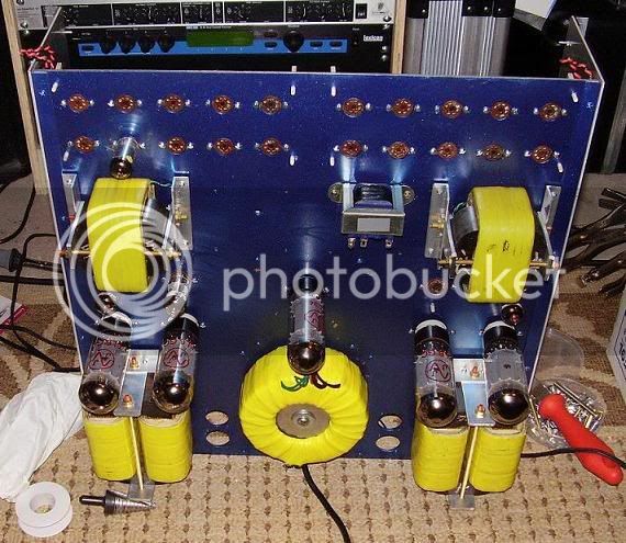
I did the power and the outputs for the GR and CV amps. The power has seven secondaries, done on  toroidal core for low magnetic field emission (I think the original had a bunch of power transformers). The GR amp trannie is interleaved (16) times (you really need an inductance meter to connect them up) and the CV amp output is interleaved eight times. I increased the number of tubes in the GR section and opted for a ratio of 8:1. I soaked the finished coils in insulation varnish which apart from the electrical benefits, preserves and prevents the transformer from singing as I like to call it. She's been running steady for a few years now with only one tube failure.
 
Moby said:
Tell me which software you use for simulating
Ah ah... this is my secret ... No seriously, I use LTspice... I don't know if it is the best, but it is free !!!  ;D
I use also some other software (glassware...)...
I got something cool with simulation... Now, I bet it's time to wind :p :p :p and to test it in reality...
 
analag said:
You're really crasy  ;)... But it makes me think I am too  ::)
10 x 6BZ6 per channel... What was the real benefit of using 10 versus 8 ? Current in the transformer or linearity ? Of course it increases linearity but your GR Amp trannies are so huge... Or maybe winter is really cold on Mars  ;D !
 
I have to slow my winding machine !!! It is so fast I can't wind close...
Anyway, I was thinking to use some copperwire I bought to do pultec inductors... But checking the specs I'm afraid the wires are too small  :mad:
http://www.block-trafo.de/fileadmin/productpdf/CUL.pdf
Mine are CUL100/0,10 and CUL100/0,22... For the primary the 0,22 one could fit but I've got a peak current of more than 140mA... Maybe I should buy some new wires or connect 2 wires in parallel... Maybe not... This is a comp SCAmp output and the amp will not deliver its full power during long times... But what can I do for the secondaries ? The first peak will charge a 0 ohm load !!! What are the diameter or the gauge of your wires, analag ?
 
Download this http://www.wiretron.com/wtsetup.exe. #26 should do it quite easily.
 
My local motor repairman is an asshole... He doesn't want to sell me anything...  :mad: :mad: :mad:

I'll have to find the different parts at Farnell as it is the simpler seller for me... They doesn't sell 26AWG but only 25AWG or 27AWG... I have to choose wich one I will use.
For the insulation varnish, I was thinking about tropicalisation varnish sold in bottles. If it is good enough, it will be easy to apply it with a paintbrush during winding on every layer. I found one with a wide temperature range (-55°C to 130°C)... I think it can do the job but if someone doesn't think the same, tell it to me  ;).
To interleave, 3M 1350-1 tape seam to be a good option.

To test the new motor of my winding machine, I winded 1000 tours. With this I got 5H inductance... Can I consider that my core have got a Al of 5µH ?

To be sure on each transformer my total primary inductance will be the same on each side (we're talking about a pushpull amp), I was thinking to wind 2 wires (A,B) at the same time on primary and secondaries on both bobins, and to connect the two bobins (1,2) like this:
primary ====  A1 serie A2, B1 serie B2
output secondary === A1 parallel A2 parallel B1 parallel B2
feedback secondary === same way than primary
Using the same wire everywhere and the ratio of the transformer ratio (a lot less than 4:1) let me think everything will be fine... Any objections, remarks ?
 
lolo-m said:
. . .
To test the new motor of my winding machine, I winded 1000 tours. With this I got 5H inductance... Can I consider that my core have got a Al of 5µH ?

Not sure !
You should measure that at some apreciable level, not with an handy meter nor a lo level impedance bridge.

Look at this:
http://www.dissident-audio.com/AutoIndex/index.php?dir=OPT_da/Mesures/&file=Check%20Box.pdf

To use OPT-da software, you must change the decimal separator from "," to "." in you regional parameters.

Yves.
 
analag said:
CJ said:
If you  want an output that will take 30 KV Hi-Pot, wind the Pri on one bobbin, and the sec on the other.

Then you have a Hospital Grade safety factor built in, which is good when dealing with tube voltages.
It will probably sound a little funky, you might even like it.
But if you overlap a layer, kink a turn, or get a core knick, or use bad wire, you will not distribute 600 VAC down the line to the next device.
Back2-1.jpg
I did the power and the outputs for the GR and CV amps. The power has seven secondaries, done on  toroidal core for low magnetic field emission (I think the original had a bunch of power transformers). The GR amp trannie is interleaved (16) times (you really need an inductance meter to connect them up) and the CV amp output is interleaved eight times. I increased the number of tubes in the GR section and opted for a ratio of 8:1. I soaked the finished coils in insulation varnish which apart from the electrical benefits, preserves and prevents the transformer from singing as I like to call it. She's been running steady for a few years now with only one tube failure.

wooooooooooooowwwwwwwww  :eek: :eek: :eek: :eek:    I want build that!!!!!
 
Back
Top