Collins 6q-1 mic preamp pics and schemo

GroupDIY Audio Forum

Help Support GroupDIY Audio Forum:

This site may earn a commission from merchant affiliate links, including eBay, Amazon, and others.

ebartlet

Well-known member
Joined
Jun 5, 2004
Messages
179
Location
Nashville, TN
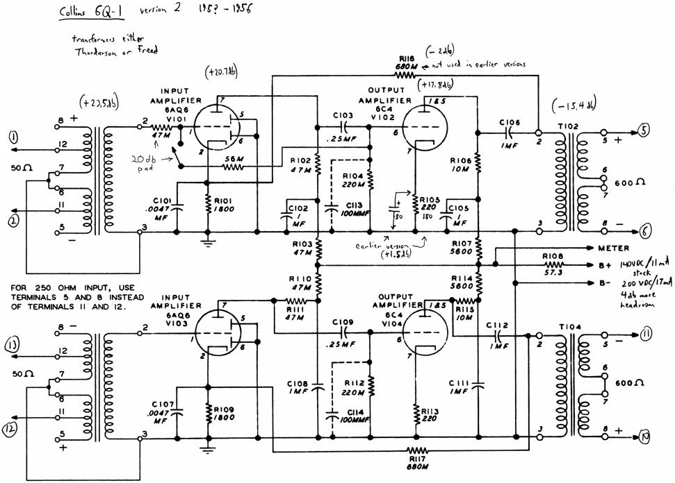
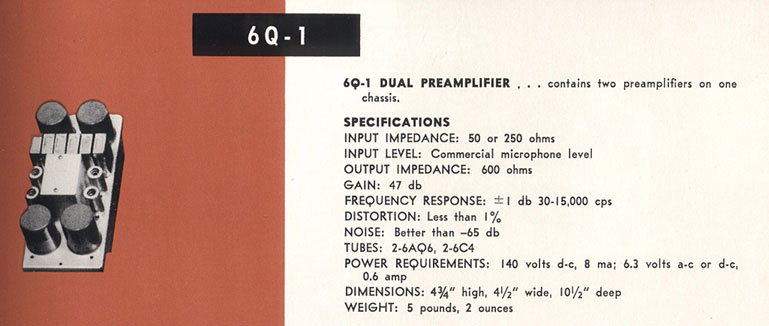
Finaly got around to building a PS for this preamp so I can start using it. Sounds pretty good during some basic tests. Definate color. Paper/oil caps and thordason trannies. The real test will be some actual recording sessions coming up soon.

You can find the schemo here:


http://www.ericbartlett.com/images/6Q1_50_250_web_schemo.jpg

Remeber M means K or u on these oldies...

Here are some pics:

collins6q1a.gif


collins6q1b.gif


collins6q1c.gif


collins6q1d.gif
 
hey did you get to use your collins pre amp if so hows she sound ?

Cheers Gary O.
 
I have not used it much, as I still have not got around to racking it. When I was experimenting with it a while back, I did some vocal recordings. The preamp is not extremely colored, but definately not clean either. I like the distortion you get when its overdriven slightly. I found that I need to use a pad when close miking anything with this pre, at least 10db, or 20db if you want to stay totaly clean. I like the mild distortion on peaks, rock and roll for sure...

I hoping to finish this thing up soon and start using it. I'll try to post some sound clips if I ever get it done.
 
Hi Doug
Nice to see you over here.
You gave me some advice on my RCA BA71 preamps some time ago. Thanks again therefore. They are still not finished since I have some noise issues going on with PSU, grounding or whatever. But vacations are soon coming up and then they will be #1 on my to do list.
:guinness:
 
I remember our discussions. Good luck finishing those soon. I'm trying to pare my projects down to a 'this lifetime' time frame. No luck yet....
 
[quote author="emrr"]Man, my schematic notations are showing up everywhere; you're welcome![/quote]

Oh! I didn't know who drew that! I got my collins pre off of ebay and archived the schematic image so I'd always have a copy. You don't happen to be the previous owner of my preamp do you? (Don't worry, I'm very happy with the decay time that the transformers "ring" for... :wink: )
 
Possibly, I've had a lot of those go through my hands over the years. Believe me, I'm not worried. There's some people who really swear by those for certain things. I kept finding consoles that were already in a state of demolition, and missing pieces, so I parted out several to get one good one up and running again.

Have you got a proper output load or resistor on them? There's nothing else I've heard quite like them. They are very euphonic and the iron is engineered with a slight (0.5 db - 1 db) rising response from 5 -15 kHz.
 
-20 db pad is something I came up with and implemented in one racked unit.  Notes address various production versions.  
2627897221_d9fd18eedd_o.jpg


1956 catalog:
2627897027_54af6ae349_o.jpg


One I racked up 100 years ago; had it's oil caps robbed before I got it.
5372523276_879100174f_b.jpg
 
Just bought one of these on eBay,  probably paid too much,  but I couldn't resist (i'm a sucker).  :p

Thanks very much for the schematic, data sheet, and photos here!

Doug,  you said "some people who really swear by those for certain things".  If you don't mind, what things?

Excited to hear this puppy.

Thanks again!

Brad


you know; certain things.  You got it at a reasonable price.  The last several I sold went for 50% more than you just paid.   
 
haha.  good to go to hear i'm slightly less of a sucker than i had thought (though it remains to be seen if the module is functional)!  i'll report back after i rack it up.  thanks!
 
Frequency plot of one having Thordarson transformers.  I took a look at my feedback pad mod, and it looks fine too.  1 dB down points of 11 Hz and 25kHz.  How's that for a 1947 amp with no feedback loop?  As PRR pointed out somewhere, the 1 mfd filter caps bump the lows up, and C101/107 is somewhat responsible for the bump on the top.  The transformer data mentions rising top response as well. 

 
Don't have any easy way to measure THD. 

No easy way to remove the boost cap.  Old giant mica directly on the socket to a buss bar.  The boost cap varies depending on the input Z; you're supposed to change it out depending on Z.  These consoles shipped wired for 50 ohm input.  This is measured with a 20 dB U pad with 170 ohm shunt, 250 ohm input taps. 
 
And how could you remove it anyway? The bass boost is just a side effect of the cap acting with output trafo inductance. The real reason it's there is obviously just for DC removal. Those Thordarsons are not gapped, are they? Probably no happy seeing 140V across the primary with the cap bypassed.

But you could just as well use 2-10uF cap and move the bump much lower if it gets in the way (it doesn't of course).

If interested in tuning the high frequency bump (C101/107), this handy calculator gives pretty accurate results: http://pentodepress.com/home/amplifier-calculators/cathode-capacitor/
 
I was responding to the comment about removing the high boost cap, not the output cap.  The FILTER caps bump the bass, due to their small size.  Ever seen 1 mfd filter caps before?  Didn't think so.  


Hadn't seen that calc before.  If needed, I tune top end with a handful of caps while looking at real-time response.  Usually necessary to do so when dealing with stereo, since vintage transformer specs are seldom terribly tight up there.  
 
Back
Top