Raytheon 5784WB as sub for AC701?

GroupDIY Audio Forum

Help Support GroupDIY Audio Forum:

This site may earn a commission from merchant affiliate links, including eBay, Amazon, and others.

riggler

Well-known member
Joined
Jan 24, 2006
Messages
1,076
Location
Pennsylvania, USA
Poking around Klaus's forum, I found this:
http://recforums.prosoundweb.com/index.php/t/2927/0/
(Go about halfway down).

And I quote:
In case anyone needs a substitute submini for use as a capsule amplifier, you might want to try out a Raytheon 5784WB wired G2+G3+P=triode. This is one of the very few submini pentodes that can be wired this way - most have G3+K as an internal connection.

Note I have not used an AC701 and can't compare if it would be a similar sound. I can only say that after testing many different submini triodes and pentodes (wired as triode), I found the 5784WB to be quite good in all aspects. IMO similar to FET sound, only the things I don't like about FET sound are fixed - i.e. it's unconstrained and open sounding while being otherwise similar.
End quote.


Can anyone here corroborate this? I'm going to try it with my M50 project if no one sees an obvious issue. A look at the datasheets...

5784WB
The 5784WB is a dual control pentode that can be used as an AF / RF amplifier or mixer.
Filament 6.3V/.2A. Plate 120 Volts / 5 mA. Gm 3200 uMhos.

AC701(k)
http://tubes.mkdw.net/sheets/128/a/AC701.pdf
Filament 4V/.1A. Plate (120V? Could use some help here interpreting the data from the sheet...)

Thanks for any info / ideas.

 
> corroborate this?

Not me.

> try it with my M50 project if no one sees an obvious issue.

Tube is tube. Why would it fail to "work"?

You already know the 5784 eats three times the heater power, so you will design for that.

> Plate (120V? Could use some help here interpreting the data from the sheet...)

The "characteristics" are taken at 40V and 60V. At quite high current.

Then Telefunken gives you "Typicals". Ub is -supply- voltage. With Ra= 50K, and 1.35mA flowing, it has thus-and-so performance. Since 1.35mA in 50K is 67V drop, down from 120V, the plate sits near 52V. But this is not critical, nor fussy. Triodes tend to find a workable condition.

The 5784 is a wonky dual-control tube, three times bigger (current) than AC701. Its datasheet emphasizes such work, and it is hard to squint what it takes to put it into low-current triode bias like the AC701. My guess is that whatever cathode resistor works for the AC will "work" for 5784, though some adjustment may be needed to set the plate near half-way up the supply voltage.

> wired G2+G3+P=triode. ... - most have G3+K as an internal connection.

You can also wire G2 as "triode plate", and ground (or cathode-tie) all that junk beyond G2. The triode properties will be about the same. The "risk" is that G2 is not rated for large dissipation, but for other reasons a mike head-amp will NOT be worked at large dissipation, so it is worth a check. Ass-uming something near 1.5mA and 60V in the "plate", that's 0.1 Watts, 5784 G2 is rated 0.6W (which is a pinch more than the AC).

In typical mike head-amp circuits, gain will be similar; and gain is not a critical spec for a mike head-amp.

AC701 has specific limits on noise. Some 5784 do, but the test-spec is not in the sheet and the meaning is meaningless. You will surely want several samples and compare the noise. Since 5784 is "highly reliable", it is not prone to dirt/crap noise like cheap tubes, and most samples will have hiss very close to theoretical. But since audio noise is not a primary concern, a few hissers may get through.
 
It's a decent sub. I put it in one of my C60s and it's perfectly usable.

Having bought ten to choose from, I compared the first two and didn't bother any further. They were both quiet enough to satisfy me for general use (acoustic guitar and such-like). Perhaps I might have found an even quieter example but, frankly, the AC701 (non-k) I had in it before wasn't really noticeably better.

I say go for it - they're cheap enough!


EDIT - Forgot to mention, it runs warmer too.
 
PRR strikes again. Thank you! I will work on the schematic changes (for heater current) and post back. I didn't understand some aspects of the datasheet and now I do! Which to me is more important than a "here you go" answer.

So I won't have to mod the plate circuitry architecture. At the most just change a resistor to get the proper drop to put me in-range (which it might already be).

By grounding G3 and plate (using G2 as plate), are you suggesting quieter operation?

MagnetoSound,

What mods did you do to use this tube? You didn't just drop it in, right??

Thanks

 
M50b?  Are you going to use a real BV11?

Looking at a B schematic I found on the web the grid is -1.6VDC fixed biased needing a clean heater supply and the plate current is marked and the voltages are marked.

Look at the curves of the 701 and compare them to the 5784wb wired as a triode(you might need to plot them yourself).  The issues are if you want a drop in for a plate out you might have to change some parts besides the heater voltage.

You need to learn to read the curves that are often in tube spec sheets.  Use Ohms law to calculate the currents and voltages.
A issue with tube microphones is that most tube curves are harder to read on the spec sheet at the voltages and currents one finds in tube microphones.

The best thing to do might be to build the tube fragment of the microphone and adjust things for the tube used to maybe get close to the operation points of a M50.

I have not used a 5784wb.  I would not worry about G3 to cathode or anode yet.


riggler said:
What mods did you do to use this tube? You didn't just drop it in, right??

With regard to the plate supply, all I did was adjust the last dropper in the RC network.

I had no problem with the existing cathode resistor(s). G3 to plate.
 
An AKG C60 is a CF circuit not a plate out like a M50.  Two cathode resistors to set the operating points and capsule voltage.  The grid resistor is connected at the node of the two cathode resistors and grid the bias voltage is generated from the voltage drop across the top  cathode resistor.  This also causes the grid resistor to "appear bigger"  to the capsule from feedback.

I would think the C60 circuit would work with different tubes and the stock resistor values, maybe not the best but it is a CF that only needs "to move" the output the signal level of the capsule.  The charge voltage might move caused by a shift on the curves.  Are you going to hear a few volts change in charge voltage?

Did you take voltage measurements before and after the tube change at the cathode and resistor nodes in the C60?
 
Gus,

I just found these "BV-11" type transformers:
http://www.aamicrophones.com/parts.htm
$45 each.

I have no idea as to their quality. Anyway, I was going to try to use the Cinemag CM-2461NiCo (U47 type tranny) but I have not looked into compatibility yet as far as loading, etc.

I have been reading a lot of tube tutorials, and yes I have been doing some MATH finally, as things are starting to make sense to me.

There is one thing that I can't wrap my head around though.

A diode tube can only conduct in one direction. I get that, makes total sense. I understand why as well. If the anode were negative, and we were trying to conduct backwards to the cathode, it would not work because we have no heater to cause thermal emission. No problem.

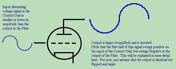
BUT how is it by adding a control grid in a triode that all of a sudden we can see a negative voltage at the plate????
I can see an AC signal on the control grid bringing DOWN the current, but how can it reverse its direction?

What I think is happening (and I think I am incorrect) is that the AC signal is amplified OVER the DC flowing through the tube, and then later, at a coupling cap, we remove the DC, leaving amplified AC as a result.

I've been working through the material here:
http://www.electronicstheory.com/html/e101-43.htm

On page 42 the author says this:
If we place an AC signal on the Control Grid of a triode, the signal swings from Positive, to Negative, then back to Positive. As it does so, the Plate Current swings directly with the Grid Voltage. If we have a fixed resistance load ( a resistor ) across the output of the Plate, we will notice that when the Plate Current goes High, the Plate Voltage goes Low. As the Plate Current goes Low, the Plate Voltage goes High. ( Ohms Law applies ... E=IR ).

I get this now. Makes sense.

BUT THEN, he says this (page 42):

ampl1.jpg


How can any current at the plate change polarity from the normal bias current?
Or am I misreading what he's saying here, and the current never does change polarity?

Thanks for bearing with me, and thanks to all of you guys for being helpful to us newbies.
 
> we can see a negative voltage at the plate?

We can't. (Usefully.)

Tube swings one way.

Audio swings both ways.

We "bias" the tube to some DC point, about half-way between ON and OFF.

Say 200V supply, we set the junction between plate-resistor and plate to about 100V.

We then wiggle the tube around that point. Say from 100V, up to 101V, down to 99V, and back to 100V. Always positive, but more/less positive.

We then "subtract" that 100V "bias". The exact bias is uncertain; however a simple coupling-cap will slowly adjust to the average bias yet still pass sudden changes (audio).

Same for a cathode-follower (which Gus says you have; and which makes tube-type fairly unimportant).

Alternatively, a choke or transformer can pass the DC "bias" and kick-out sudden changes (audio) to a load.

> I compared the first two and didn't bother any further. They were both quiet enough ... Perhaps I might have found an even quieter example

No.

In a box of 100 tubes, 95-99 will hiss "insignificantly" more than theory (cathode resistance 1/Gm and temperature) would suggest, and 1 or 5 will hiss "significantly" more (5dB-10dB).

In a box of cheap modern tubes, maybe 50% (or even all) will hiss bad. In a box of Golden Age Premium tubes, maybe none.

If you have just one tube, Murphy's Law ensures it will be a hisser. But you can't be sure, without more samples to compare (or very tedious tests).

If two premium tubes sound fine, low-hiss in a microphone, they are probably both 1dB-2dB above theoretical minimum hiss. You could go through all ten and find 1.3dB, 1.7dB, 1.4dB, 1.9dB... all audibly the same hiss, and insignificantly different from "perfect". Or you might find one with hiss 7dB above perfection, 5dB above the others... and after hearing the others, this one would stand out as "bad". Maybe not bad for rock&roll stage show, but not your first choice for acoustic studio work.
 
PRR said:
> I compared the first two and didn't bother any further. They were both quiet enough ... Perhaps I might have found an even quieter example

No.

In a box of 100 tubes, 95-99 will hiss "insignificantly" more than theory (cathode resistance 1/Gm and temperature) would suggest, and 1 or 5 will hiss "significantly" more (5dB-10dB).

In a box of cheap modern tubes, maybe 50% (or even all) will hiss bad. In a box of Golden Age Premium tubes, maybe none.

Thanks PRR, for this insight. I must admit I am more used to trawling through boxes of cheap modern tubes or sticking with the Golden Age NOS than I am working with with these JAN sub-minis, with which I am relatively unfamiliar.

I am beginning to understand why these tube types are becoming popular with modern mic manufacturers!


PS @ riggler - I've also had good results with 5840 and 5703. The 5840 has a round base, rather than flat, which can make dressing the leads somewhat easier - or not, depending!
 
PRR,

Thanks for clearing that up.

Actually, I've got a plate-out, it's magnetosound that has a CF.

If I take this a step further....

So we can play with different transformers to give a different load and resulting voltage to the plate?

And it's the ratio that will set our output impedance given whatever the input impedance of our circuit is.

For example, I've already ordered a Cinemag CM-2461NiCo. These have a 6.5:1 ratio.
The original BV11 is a 5:1 ratio transformer.

So I surmise that the Cinemag might be okay to use since the ratio is pretty close. I say *might* because I'm assuming we can use a resistor to impedance-match the circuit to the transformer.

Now, it seems not too difficult to calculate the resistance of the circuit around the output (plate). But how do you turn that into impedance when it comes time to match your circuit to a transformer.

I am sorry for the derailing of the topic but things are clicking here...
 
> assuming we can use a resistor to impedance-match the circuit to the transformer. Now, it seems not too difficult to calculate the resistance of the circuit around the output

Audio is very rarely "matched". Gain is cheap, mis-matched Lo-Z/Hi-Z interfaces are much easier to work with, tube distortion drops when load is raised.

But gain is not free, and a little precious in a tube mike. You'd rarely want to waste any with "matching resistor".

I'm quite confused, C60 M50 '701 5784 AF CF.... but I'll plow.

As Gus said, you may have to plot a pentode's triode curves. Page 8 of 5784 data can be read for a constant G1 voltage, plate and screen at 60V and 90V. The sum of currents is like 1.25mA and 4mA, for 30V shift of plate voltage, so plate resistance in this area is like 10.9K. Since we will probably work the mike closer to 1mA than 4mA, I'll round-up to 12K. For 120V supply, 60V on plate, and 1.5mA current, the DC feed resistor is 40K. The effective plate-node impedance is 9K.

What is the load impedance? What IS the load impedance?

There have been mike inputs with very high impedance, hundred K. Usually a pair of Phantom resistors sits there all the time, limiting it to 13K. Very occasionally you see a mike input swamped with 150 ohms (especially when working under your own radio transmitter). 2K is conventional.

And what-all else? 6 to 600 feet of cable, maybe? 200 to 20,000pFd capacitance. At 20Hz this is nearly infinite impedance; but 20,000pFd at 20KHz is 400 ohms.

So pencil the "load" as maybe 13K, often 2K, but 400 for long lines at the top of the audio band.

Taking just the nominal 2K, your 5:1 and 6.5:1 irons present 50K or 84K to the tube's 9K node. The 6.5:1 has 1.3:1 more step-down, but also throws higher Z at the tube, which will raise its gain a smidge. For low THD, we would like total load (including the 40K DC resistor) to be "higher" than plate resistance. 40K||50K is 22K, which is nearly twice as high as 12K, so it's fine. At 20KHz in a very long line, we have 8K load on the 9K tube, so there will be some top-loss and at high level, some THD. If, in a specific situation, the 5:1 iron "has trouble" with ten 50' cables, the 6.5:1 will have the same trouble at eleven or twelve 50' cables... not a significant difference. And you may protest that you don't own that much cable or have a place to run it to.

The main thing when switching tube types (after pinout and heater and max-ratings) is to get the DC operating point roughly the same. This means leaving the B+ and the load resistor alone, and tinkering the cathode bias resistor until plate voltage is in the same ballpark.

Usually variations of 30% make little difference. Gus says this C60 gets capsule bias voltage from tube operating point. 10% shift of voltage is ~~10% shift of sensitivity, which may be unimportant; but 30% shift might have more effect.
 
Found in the meta

http://www.sdiy.org/oid/mics.html

you can find the Neumann M50 AC701 and AKG C60 AC701 and the M250b(easier to read)

I plate is often less than 1ma.
 
PRR said:
The main thing when switching tube types (after pinout and heater and max-ratings) is to get the DC operating point roughly the same. This means leaving the B+ and the load resistor alone, and tinkering the cathode bias resistor until plate voltage is in the same ballpark.

Would this be the case in the C60 CF circuit? As there is effectively zero AC impedance at the plate (due to the filter cap C6 after the final dropper, and the directly coupled plate), and presumably the 1.5k is setting feedback(?), it would be the 82k in this case which is tinkered?

How will that affect output impedance?
 

Attachments

  • AKG C60.jpg
    AKG C60.jpg
    192.4 KB · Views: 179
> a cleaned up M50b schemo:

Trap!

This triode is "fixed bias". There is a solid +4V DC source (heater). The cathode is tied up at +4V. 200K and 300K divide that to +2.4V at R1 and grid, or 1.6V negative of cathode.

Change to a 6V heater, bias will be different.

In this case, nothing interacts much. Tinker R5 until your plate node is back near 40V-45V above ST pin 3 (ground).

Man, that heater supply better be VERY clean, 'cuz its crap couples 100% into the full gain of the system.

The OT type and detailing are more important than the ratio. A low ratio gives a hot output but will top-droop in long cables. A high ratio gives lower output, which may not overwhelm the next stage's hiss, and is a tougher winding-design problem. 4:1 seems low, 10:1 seems high, in between you can choose by color or brand.
 
> the C60 CF circuit
> presumably the 1.5k is setting feedback(?), it would be the 82k in this case which is tinkered?


No. 82K is the "plate resistor", just moved around. It is a good size for the tube to fight against. 1.5K is the cathode bias resistor. It has large leverage on operating point, though very small drop.

> How does that affect the output impedance?

Hardly at all. Cathode impedance will be 500r-1K or so, not exactly known, but very much smaller than the load impedance, which we know from the sizes of C7 C8C9 must be many K.
 
PRR said:
1.5K is the cathode bias resistor. It has large leverage on operating point, though very small drop.

Ah, of course.

Gus said:
The grid resistor is connected at the node of the two cathode resistors and grid the bias voltage is generated from the voltage drop across the top  cathode resistor.

Thanks to you both, you guys are fab!
 
This triode is "fixed bias". There is a solid +4V DC source (heater). The cathode is tied up at +4V. 200K and 300K divide that to +2.4V at R1 and grid, or 1.6V negative of cathode.

Change to a 6V heater, bias will be different.

I was wondering why there was a node connecting heater supply and cathode. Gus in another thread has already suggested a very clean supply.

Tinker R5 until your plate node is back near 40V-45V above ST pin 3 (ground).

Fair enough. So I tweak the voltage divider to bring the plate voltage back down. I have another question on how the plate "sees" R5 but will save it as I am going to re-read something to make better sense of it, so please don't give me the answer right away!

Now, C3 is blocking DC from the transformer. Why do we need C2 at all though?? Smoothing? I'll be honest, there's a lot more to this schematic than the examples I've been learning from, making it hard to know where to start when trying to calculate voltages / current levels. (For instance, R1-R7 all being so close, figuring what is dividing what... looks to me like the plate should get positive voltage through R8.

nothing interacts much...

...because now the cathode is being "tamed" (for lack of better terms) by the consistent presence of heater voltage, right?

So how is the tube being wired now? G2 and G3 tied to plate? Disconnected?


Gratefully yours,
Riggler


Latest posts

Back
Top