Restauration of STUDER 169 console

GroupDIY Audio Forum

Help Support GroupDIY Audio Forum:

This site may earn a commission from merchant affiliate links, including eBay, Amazon, and others.

roginator

Well-known member
Joined
Nov 7, 2005
Messages
467
Location
CROatia
whell this small beast have great sound... and since i keeped one of few I had.... i spend some time using it in studio.

I notice that channels are actually very different in color and volume also noise level was different on each channel..
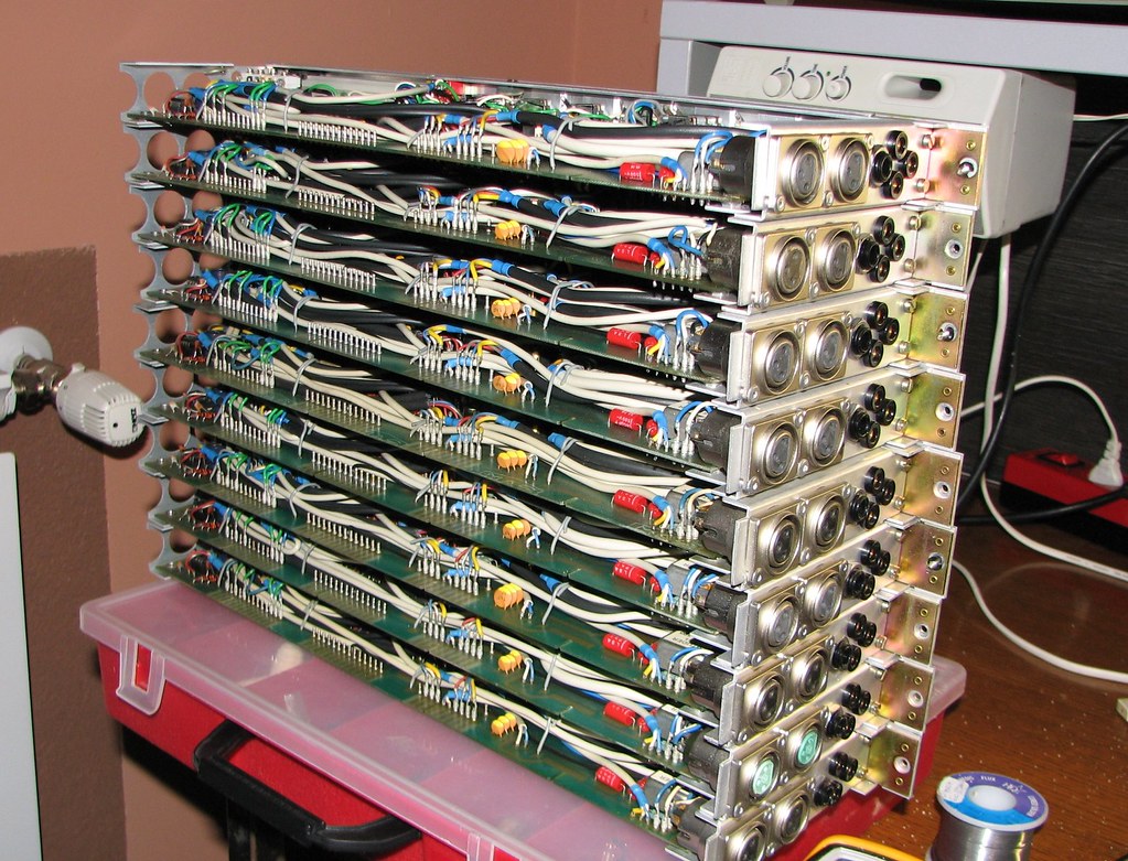
in studio I use it as preamps, expander for more channels to my MCI 500 and FX returns since my MCI have only 4 //

Studer is in use as 12 ch desk!!!

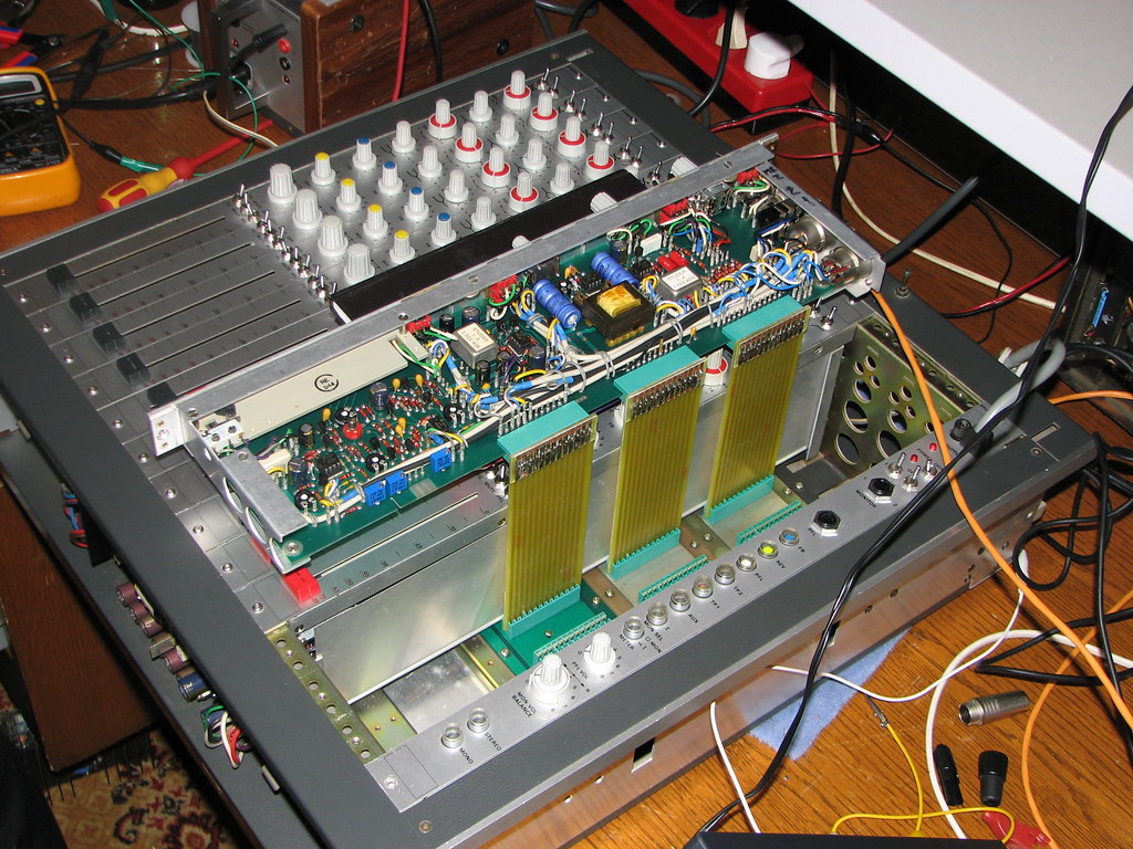
after some time I decided to do complete restauration of console

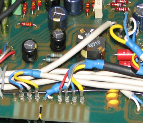
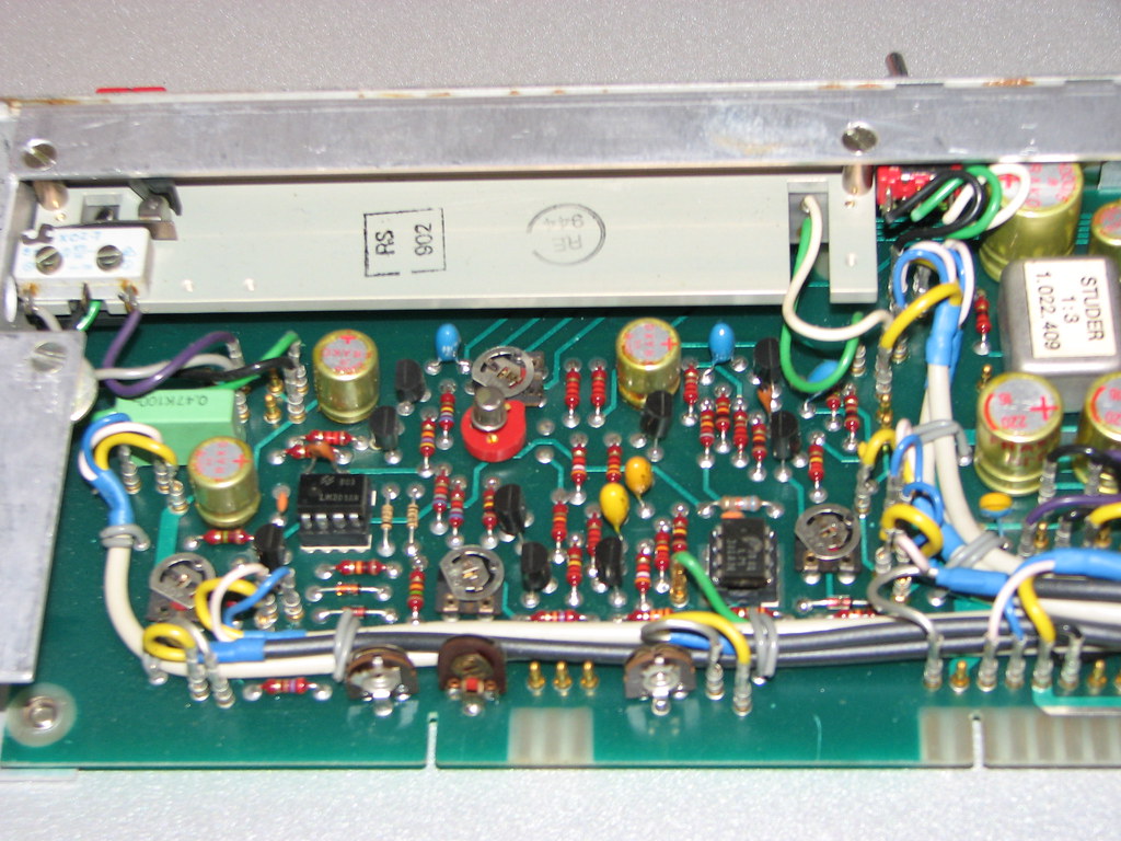
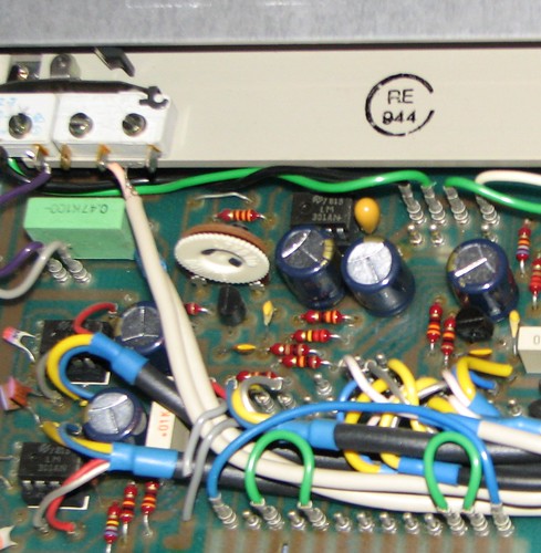
- For all channels recaping of electrolytic caps and tantalums is MUST!!!
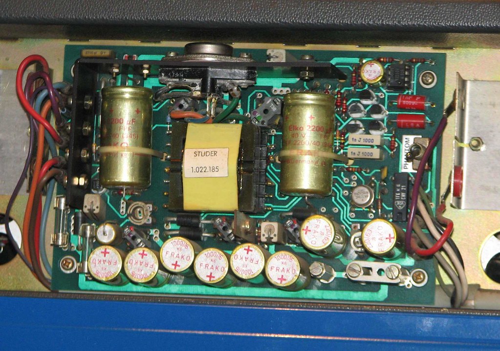
after I open console and notice that 80% of FRAKO caps are lets almost dead i ordered panasonic and elna caps

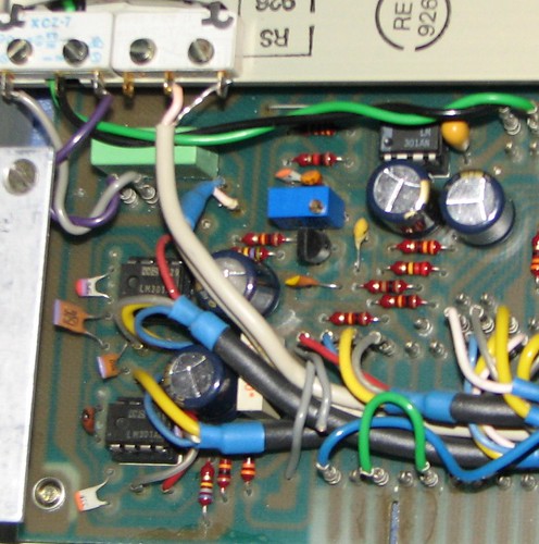
almost all frako caps looked like this!!!
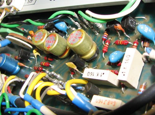
4423530992_c18b31fef8.jpg


SCARY!!!!!


I/o Module Caps list is:

100uf/25v x8
220uf/25v x5
47uf/16v Tantalum x1
10uf/25v Tantalum x4

Cleaning faders is MUST !!! top end is in 90% dirty and make crackle while useing it ..so I cleaned that too

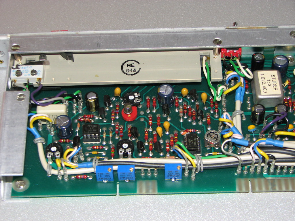
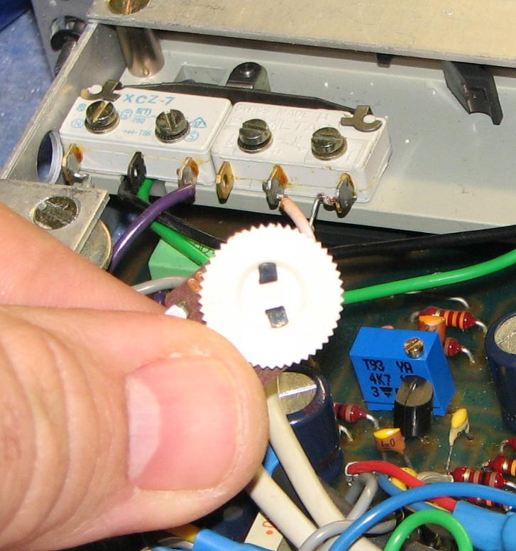
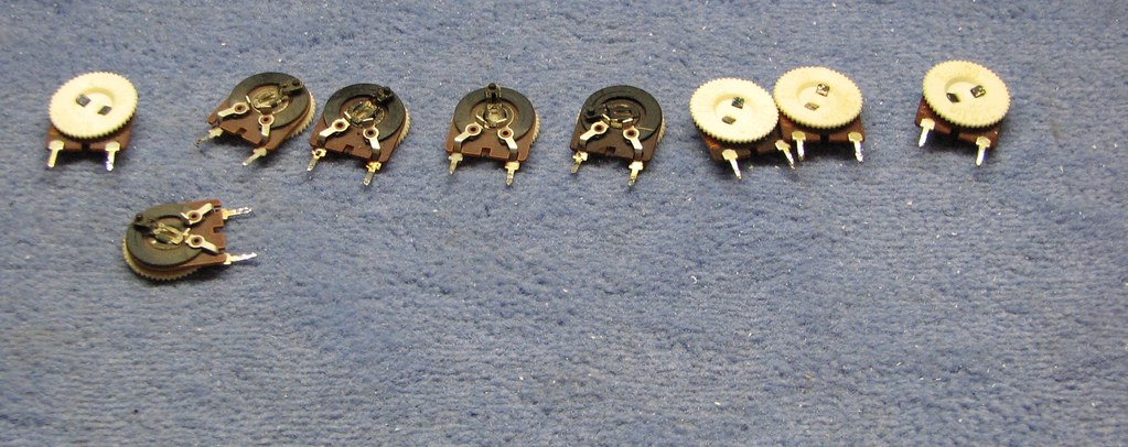
also I notice that poor made trim pot is used in I/O module for Fader Buffer calibration RUWIDO 4k7 ... I relpaced it with multiturn Bourns one!!!  
4423550448_4d4b5dedec.jpg

4422785847_e2d8e02c53.jpg


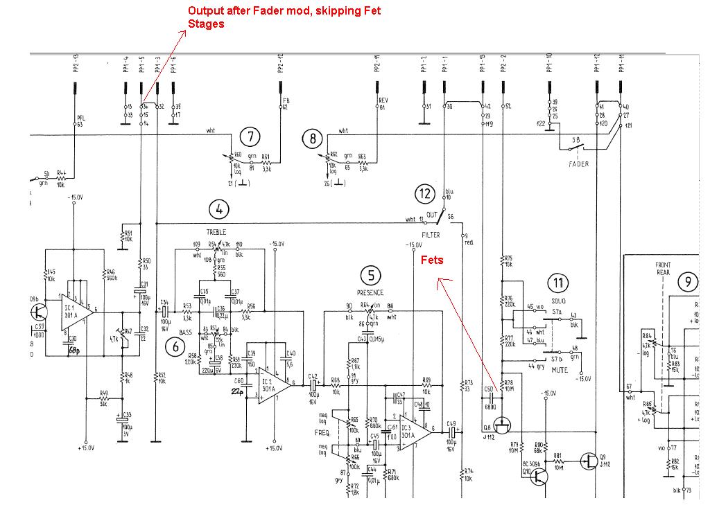
still have to demagnetize transformers on modules and mod it for direct output!!!!!

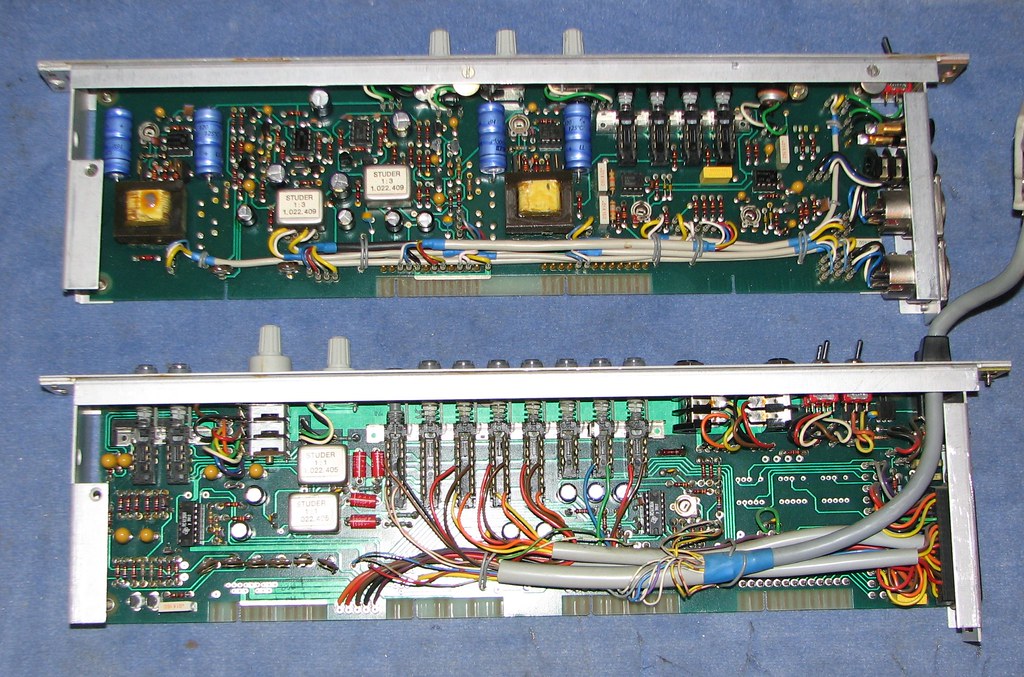
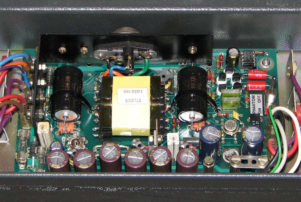
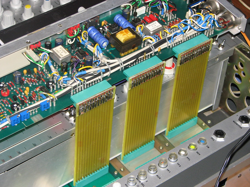
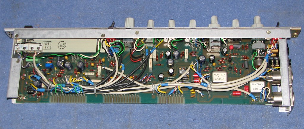
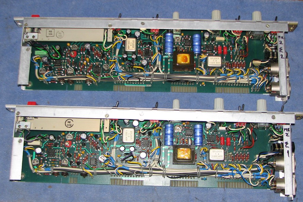
STUDER 169 i/o module after restauration!!!!
4423564646_18d0be6e9e_b.jpg


169 MASTER MODULES!!!

List of recaping of each summing module !

100uf/25v x5
220uf/25v x3
1000uf/6,3v x1
1000uf/16v axial x2
0,47uf/35v Tantalum x1
3,3uf/25v Tantalum x2
6,8uf/25v Tantalum x1
10uf/25v Tantalum x3

also cleaned faders and thinking of replacing trim pots and recalibrating modules!!!!
4423584980_083decf10c_b.jpg


thanks Damir will do recapp and other things in the future, one question: using reverbs units or other hardware as inserts on the 169 channels, is not clear to me how to do it, on the manual says connect the output of reverb unit to the hi level input (xlr)
is correct or there is a better way?

ciao filippo
 
on i/o modules REPLACE R47 trim !!!!!!!!!!!!
it make big difference on REV SEND, and output of each module in db!!!!!!!!!!!

that RUWIDO are BAD!!!!!!
4423029963_b8e54ab0da_o.jpg

4423794508_1b6d04d8fe_b.jpg

 
pippo64 said:
thanks Damir will do recapp and other things in the future, one question: using reverbs units or other hardware as inserts on the 169 channels, is not clear to me how to do it, on the manual says connect the output of reverb unit to the hi level input (xlr)
is correct or there is a better way?

ciao filippo

Hi Filipo

whell you can connect 2 ways!!!

If you wanna use pre fader send ...use FB if you want post fader eq use SEND REV....

connect input of your reverb to talk back module .... on back of that modules is FB and SEND REV summing output (XLR out balanced) ... on talkback module also is MASTER send control for FB and SEND REV.
return output from your reverb into master section modules (XLR balanced inputs)... on top of that modules are line inputs balanced to use as FX return.. select pan and level and go!!!! :)

or you can return signal from reverb to 2 of channels and use them to color reverb with fx :)
 
Hello, great job and thanks for sharing with pics. I had one of these before and it sounded quite good but I bet yours sound even better now after the restauration.
 
This is bit crazy...

I have few modules from different revisions of 169 in my console... on 2 modules I dont have that BUFFER FADER TRIM.. and output on modules are different..removed factory trim and recalibrated all modules!!!!!

BINGO!!! INPUT MODULES ARE PERFECT!!! still to demagnetize tomorrow!!!!!! and route direct outputs from preamps!!!!!

bunch of I/o Modules ... you can see different revisions by different XLR colors on back of modules
4423796006_3d0b6107bd_b.jpg


ok here are Talkback module and Control room module
4423871296_0556efcb30_b.jpg


Recaping list for talkback module:

100uf/25v x4
220uf/25v x2
1000uf/6,3v x2
1000uf/16v axial x4
47uf/16v Tantalum x3
1uf/25v Tantalum x2
3,3uf/25v Tantalum x2
10uf/25v Tantalum x5

Recaping list for CTRL room module:

100uf/25v x2
220uf/25v x5
100uf/16v Tantalum x6

on CTRL room module remove RC 4136N from IC socket and clean pins ..they are heavy oxidated.

Recaping list for bridge meter:

220uf/25v axial x8

 
Modification for direct out :

I used idea that user 37518 explained in his racking design
....

Remove pins from patch bay that is on back of modules from connection points 95, 96, 97 on PCB .... and keep 98 yellow wire (on my modules) in place
that way you free patch points for use as unbalanced out!!!!

PBC is top mid connection point of patch bay on back of module (red wire)... extend wire and connect to connection point 14 or 15 on PCB under fader. (SIGNAL OUT)
PCM is lower left patchbay point (if looking from back)  (blue wire) ... extend it and connect it to ground point anywhere on module where you like it...my module have ground point above connection point 98.. so i used that one!!!

leave PBL white wire patch point free...(maybe for future use)

thats it you have unbalanced exit from each i/o module !!!! thanx user 37518!!!!
4423989548_9947c371ca_o.jpg


Before modification:
4423397985_8a1c484bee.jpg


After modification...follow red extended wire:
4423397661_9c3f923989_b.jpg

4424161076_8fc1f9e47c_b.jpg

 
recaping of DC/DC converter in front of frame

how it looks original
4320571616_4e10d6bae5_b.jpg


Recaped
4423280265_8259ca9cbe_b.jpg


Recaping list of DC/DC converter:

47uf/50v x1
220uf/25v x1
220uf/63v x2
1000uf/25v x6
2200uf/40v axial x2

 
OK now de-magnetizing!!!!!!!!

some time ago I found on this forum  THANK you 1954U1

-------------------------------------------------------------------------------------------------------------------
quickly done the de-magnetizing procedure suggested:
sine wave at 30 Hz, 30 secs sweep 0V-3V [point of saturation], 30 secs sweep 3V-0V.

-------------------------------------------------------------------------------------------------------------------
so now 28 input transformers to de-magnetize :eek:
 
That is great work on a great console.
What happened to all the wiper legs to those old pots?
And you might consider replacing those RC 4136's, at least in the mix/monitor section with something like a LT1359 or LM49740.  Jim Williams is big on this type of swap, and eliminates the coupling caps at the output.  I am going to try it on a certain British console that just don't sound good because it is loaded with TLO74's.
Mike
 
OK .....

cleaned frame.... looks like new.... ready to be loaded!!!!
4479829193_693c9751a6_b.jpg

4480473666_c3ff1bd580_b.jpg


whell ... after that tried to recalibrate all trims on master modules and realized that allmost all are scratchy and no good to be used....

whell more work replacing trim post!!!!!! not just RUWIDO on i/o channels ... I replaced em all on console!!!!

.. well ok I want studer in perfect shape!!!!

example BEFORE change of trim potentiometers  ... BAD, DIRTY, OLD....
4479847619_40d695af0f_b.jpg


and after .... NEW, FRESH.....
4479844679_323308cf9b_b.jpg


weekend is finish!! ..I will recalibrate and test console
 
GOOD

hahahhahaa I just realized I forgot to replace 1 ..... 22k .... hehe thanx to camera!!! .... I go fix that too..
 

Latest posts

Back
Top