This is what I do Igor. Peter's layout is very, very similar.Igor said:Hi Jeff, +1 for the tabs
But, for future, will do all 500 stuff with 18 pin option, to be on safe side twice.
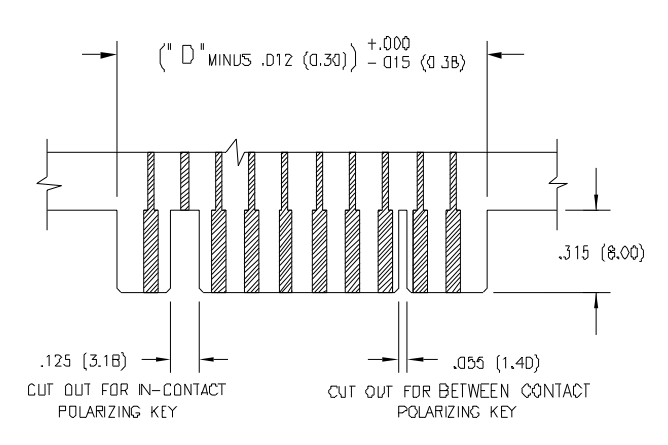
Can you please post exact dimensions for this cut at "pin16"?
Sorry to all of our metric friends. :'( I guess this is when 25.4 is our friend!
")

Cheers, Jeff