[silent:arts]
Well-known member
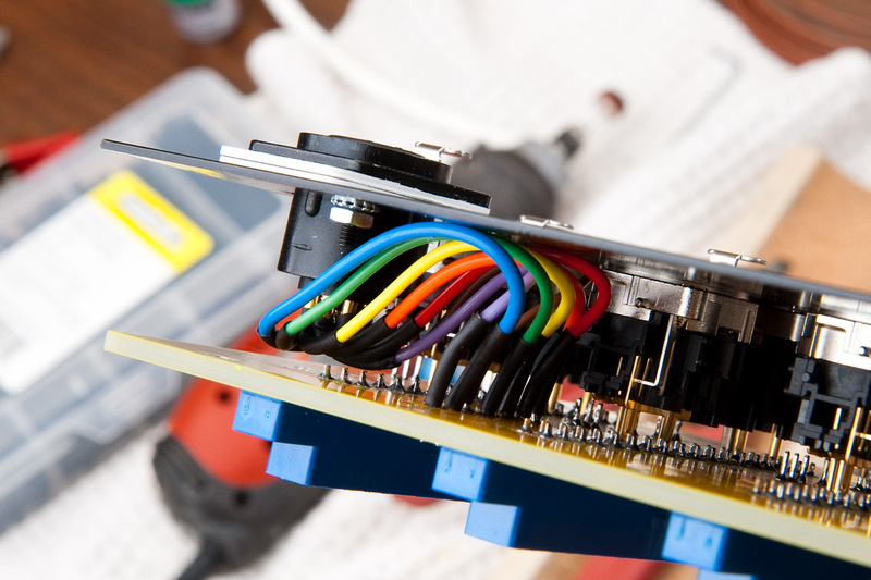
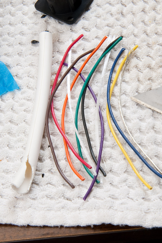
the original API L200 PSU uses 20AWG btw,
but not marine grade
but not marine grade


'Chunger, last I heard from Cemal, he was to pick up all the PSU cases at the end of this past week. If that did happen, I would gather that I will have those cases to disperse before you could get a lesser case from Parmetal. I understand if you want to move forward. I just saw this and figured I would let you know.chunger said:...Patience is wearing thin on the official 51X Alliance PSU metal kit shipping to the US. I haven't heard anything new about progress on that front even though I've been keeping a close eye on the thread for any new developments...
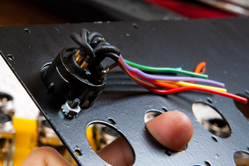
Ptownkid said:Is it physical size or rating that you are concerned about on the cable...that 24awg is rated at 300V and will carry the load perfectly fine in short runs.
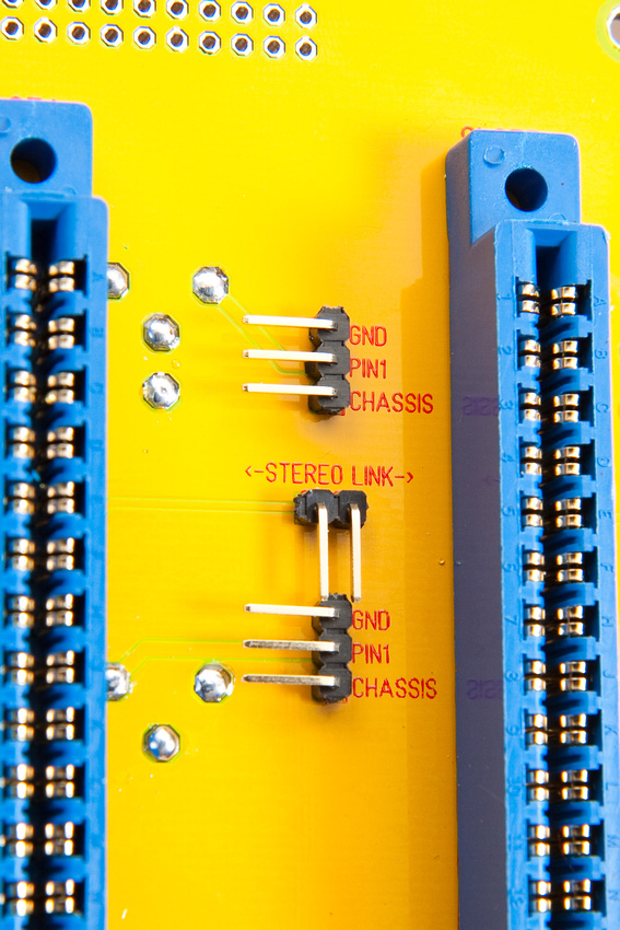
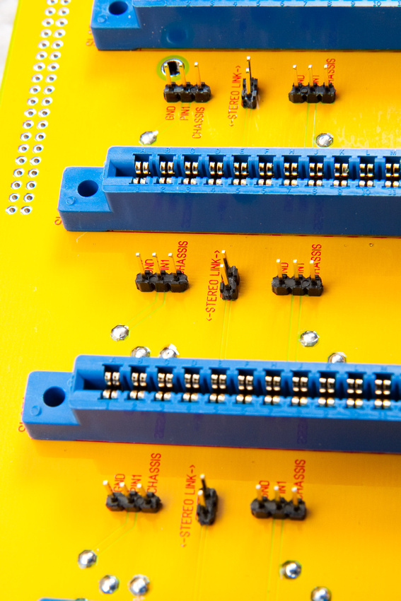
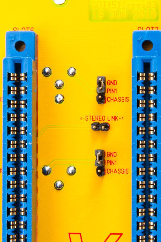
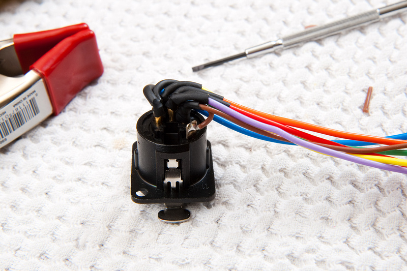
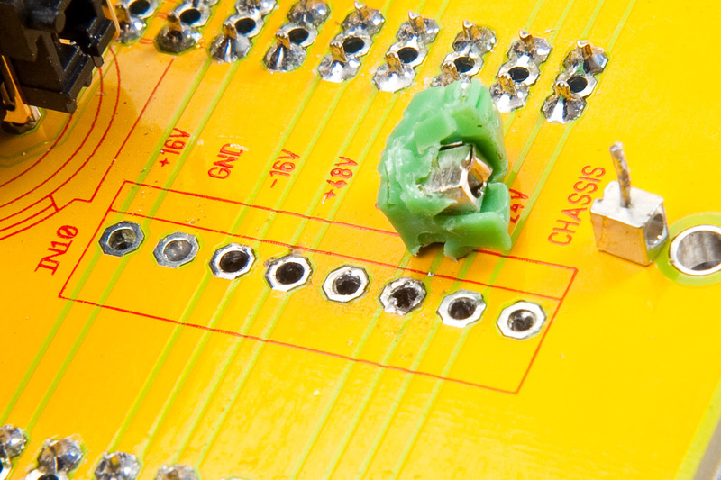
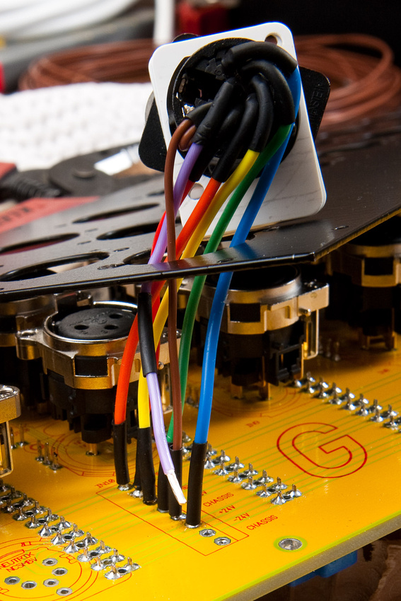
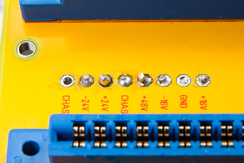
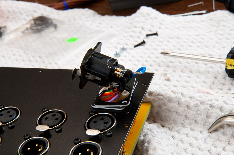
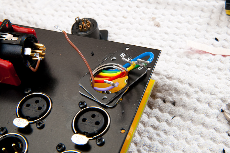
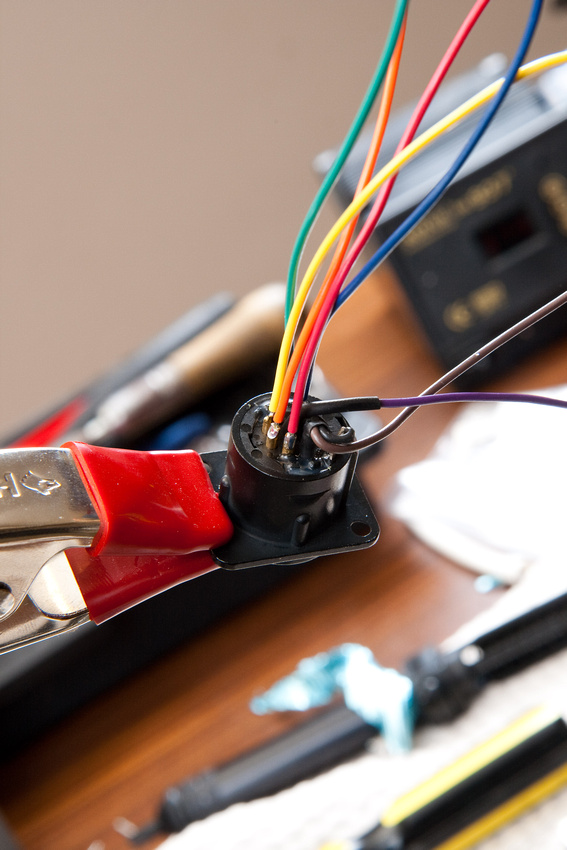
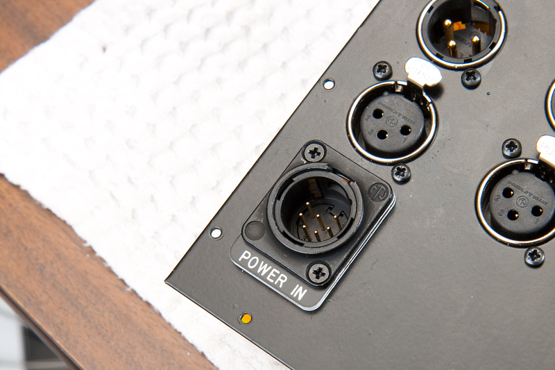
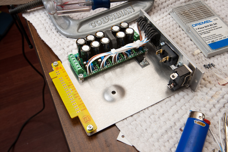
Volker is right on this. In this type of configuration pin #1 should go to chassis as per the Rane documents. The shunts and headers really make it easy to swap if need be but you should start out with pin #1 to chassis.chunger said:...I read conflicting reports on forum about which way to ground. Silent-arts seems to advocate pin 1 to chassis while jsteiger seems to advocate pin 1 to ground. Well, I guess that's why I put the headers in. For now, I have pin 1 to ground, but I'll probably put pin 1 to chassis and then check to see if phantom power is working properly as my feeling I get from reading suggests this is a more "proper" way to do it. If I get noise or phantom power problems, I can change it over to the other configuration without much problem.
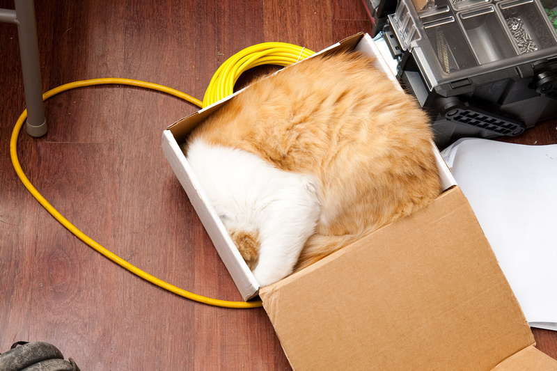


One of my new favorite sayings is "humans win!!".Ptownkid said:Go humans! ;D
Enter your email address to join: