You are using an out of date browser. It may not display this or other websites correctly.
You should upgrade or use an alternative browser.
You should upgrade or use an alternative browser.
Amek Neve 9098/9098i Query
- Thread starter danielle
- Start date


Help Support GroupDIY Audio Forum:
This site may earn a commission from merchant affiliate
links, including eBay, Amazon, and others.
G
Guest
Guest
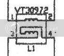
it look sto my untrained eye as a transformer
If it's a 9098 it will be the output transformer as the input is electronically balanced
The numbers refer to the pins on the transformer
If it's a 9098 it will be the output transformer as the input is electronically balanced
The numbers refer to the pins on the transformer
peter purpose
Well-known member
I'd hazard a guess that that there is an inductor my preng.
Samuel Groner
Well-known member
Did I miss the supergreen schemo? Could you post it here or shall I drop you a PM with my e-mail?
Could be a common mode choke.
Samuel
Could be a common mode choke.
Samuel
Bookkeeper
Well-known member
It is an input double toroidal inductor of the 9098 micpre. Connected probably in "diferential" mod to cut rf interference.
bk
bk
[quote author="Samuel Groner"]Did I miss the supergreen schemo? Could you post it here or shall I drop you a PM with my e-mail?
Could be a common mode choke.
Samuel[/quote]
Hi Samuel,
Calling it the "Supergreen" is my little joke as the Amek 9098 was designed by Rupe Neve & the Amek Mozart on which PeterC based the green mic pre. I'll link to it later so you can see the similarities & why I call it the *SuperGreen".
Thanks people,
Danielle
chimimic
Member
I think as Bookkeeper : this double inductance is only here to reduce RF or other unwanted signal that can come from MIC input.
G
Guest
Guest
[quote author="danielle"]

Here's a quarter of the "Super Green".
[/quote]
It is not standard neutralisation transformer. They have
paralel winding. And
schematics highlights it by inner connection drawing.
For RF interferences there are ferrite beads at input.
And 1k5 as bypass is not much...
It is simple lowpas filter. With inductance four times
higher that you measures at one winding of VT 30972,
This filter is loaded by (3n3 + 390 R)//2n2//10k.
This type filter can be Chebyshev and can improve noise ratio at high frequencies.
Only on the paper...
xvlk
Winston OBoogie
Well-known member
...
Thanks for all the responses everybody. They were greatly appreciated.
It's from the "System 9098"series, which, as no doubt some of you are aware, preceded the "Pure Path"(tm)series. The "Transformer Like Amplifier" sound of these units is apparently not something everyone agrees with. :roll:
I'll give Carnhill a try on the VT....... as well.
But is it worth the effort? What would be the "real world" advantage?
As xvlk said: "Only on the paper..."
Danielle
> what the following symbol is?
A transformer.
BUT: it is connected "funny" in a push-pull path. It couples any signal in one side into the other side, backward (note the swap on pins 3 and 4), so it cancels the input signal.
If you did this with an "audio" transformer, you would get no signal.
So what it has to be is an RF transformer. At audio frequencies it is a near-short (probably a couple ohms). At radio frequencies it starts coupling and working and cancelling the input, keeping annoying radio stations captured on long mike wires out of your audio.
In most studios, radio won't be a problem. And it doesn't serve any other function. And it hasn't been a common part. So you rarely see it in DIY or in low-price gear. For a quick-build: short it out. Omit the funny transformer, and replace R4 R1 with shorts or 47Ω resistors. Of course when you sell such things for a lot of money to customers in all sorts of nasty places, you have to think about worst-case situations and add protection for the customer who works in the shadow of a radio tower. That's why Amek put it in. When you buy such radio tranformers in case-lots, the price is a lot cheaper than one unhappy customer.
Carl_Huff
Well-known member
I'd sure like to get my hands on a higher res scan of that mic pre circuit.
Any chance of that??
Any chance of that??
[quote author="Carl_Huff"]I'd sure like to get my hands on a higher res scan of that mic pre circuit.
Any chance of that??[/quote]
Yes; there's a good chance. Unfortunately the ISP which I share with two other members who live nearby doesn't have free web space so I can't host them.
If someone were willing to host them I would be happy to email them for loading so everyone can have access.
Danielle
Any chance of that??[/quote]
Yes; there's a good chance. Unfortunately the ISP which I share with two other members who live nearby doesn't have free web space so I can't host them.
If someone were willing to host them I would be happy to email them for loading so everyone can have access.
Danielle
Kev
Well-known member
send to me and I'll post it
Samuel Groner
Well-known member
Isn't this one of Rupert's "Transformer Like Amplifier" stages?
Here's what RN said about his TLA design:
It's just an instrumentation amplifier, which is pretty standard, but I bootstrap the inputs to give each leg a very high impedance to ground. The two inputs are tied together with a 10 kOhm resistor, which turns it into a bridging input. If you feed a signal between one leg and ground, and leave the other leg floating, you get no output, because the two inputs are now tied by a 10 kOhm resistor, and in effect, they're commoned. You have something like 15 MOhm input impedance between each leg and ground, and 10 kOhm between the two legs. So the differential signal is down to about -60 dB. The circuit behaves like a transformer.
...
So you've got a differential amplifier, and you need to make sure that frequencies above audibility, where you are getting into high frequency interference, are effectively shorted together so that common mode interference is reduced. I use a little differential input coil for that, which also serves as a filter. It's a little bifilar wound coil on a small toroid, one coil in series with each leg. It has a 3 dB down point at 200 kHz, so that up to 200 kHz it is a true differential input. Above that, it's like a brick wall and pulls everything into common mode, so that now the common mode performance of your amplifier really comes into play, and nothing gets trough.
Now, can you tell me the advantage of this coil over a simple cap between the two inputs? Wouldn't that "pull everything into common mode" as well?
Samuel
[quote author="PRR"]> what the following symbol is?
Omit the funny transformer.... [/quote]
Thanks PRR,
Apparently the consensus from a couple of esteemed members who have worked with this micpre "basically" agree with you PRR.
"Works fine without it."
Thanks to all,
Danielle
Omit the funny transformer.... [/quote]
Thanks PRR,
Apparently the consensus from a couple of esteemed members who have worked with this micpre "basically" agree with you PRR.
"Works fine without it."
Thanks to all,
Danielle
Kev
Well-known member
Danielle,
as requested
http://www.diyfactory.com/data/system_9098_micpre.jpg
as requested
http://www.diyfactory.com/data/system_9098_micpre.jpg
Similar threads
- Replies
- 2
- Views
- 785
- Replies
- 13
- Views
- 1K