Different differential

GroupDIY Audio Forum

Help Support GroupDIY Audio Forum:

This site may earn a commission from merchant affiliate links, including eBay, Amazon, and others.

PRR

Well-known member
Joined
Jan 30, 2010
Messages
11,143
Location
Maine USA
There are many ways to skin (or shave) cats. The "instrumentation amp" layouts are not the only way to extract a weak differential signal from common-mode noise.

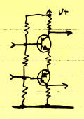
Believe it or else: this is a differential amplifier:
Stack1.gif

Stack1.gif


I found this in a 1967 book. You can take output from either collector, or from both. It isn't good for sensing DC equality, but we don't hear DC. It has some interesting properties for audio. For one: while it is differential, it isn't push-pull. It is very much a single-ended amplifier, even-order distortion is not cancelled.

With a single stage of transistor(s), gain and linearity is not that great. Compounding the transistors with a CE-CE pair is better. Output impedance is high: for driving lines it wants a buffer.

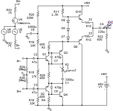
Here's the idea adapted to +48V power:
Series-Mike-1.gif


Power consumption is about 24mA. The buffer could be changed to Class A but if it might see a true 600Ω load then power demand would have to be much higher.

R29 R30 are there mostly for simulation. In real use these would be 6K8 switched to +48V or to ground.

Most caps have a steady DC bias, which will keep electrolytics well-formed. The exception is the input caps: if used with Phantom voltage then these caps must be non-polarized.

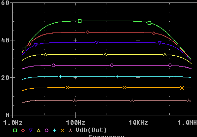
Maximum voltage gain is about 62dB and not very linear. I suspect it should not be worked at more than 50dB gain. R2 sets the gain. Values of 3.5, 8, 16, 35, 74, 170, 470, 10K ohms gives gain from 50dB to 8dB in about 6dB steps. These values are really too low to get with a pot, use a switch and fixed resistors.

Gain and frequency response plot:
Series-Mike-2.gif


At the highest gain, response is -1dB at about 20Hz and 20KHz. At lower gains it is better. Possibly too good on the high end: without the 470pFd caps the gain extends beyond 10MHz.

Distortion is not that low but very simple, a mix of even and odd order, generally mostly even and mostly 2nd and below 0.1% except at very high output level (near clipping). It will make 10V in 600Ω, about +22dBm.
 
> what transistors do you suggest?

Not fussy. Matching is pointless, Beta not very important. One of the transistors could see nearly 48V so they may as well all be 50V-60V types. 2N3904/2N3906 would be fine.

For lowest noise from microphones, the input devices should be large area, something like a 500mA hi-gain Switch, the 2N4401 and its complement. These could be rated as low as 12V: I don't think they will see more.

The noise level with good fat input devices will be very low for gains from 50dB to about 28dB, below the thermal noise of a 150Ω resistor. At gain of 8dB the noise figure rises to about 6dB, not bad (some mike amps reach NF=20dB at very low gains).

Where this might really shine is big hot condensers like AKG-414. You never need even 50dB gain to record music with 414 at normal line level. You may need as little as 8dB gain to keep an un-padded 414's signal from clipping in the mike-amp. And if you had a 140dB SPL source, the 414 and this amp would deliver a 120dB range from near clipping to the hiss-level (about equally 414 self-noise and mike-amp noise). The distortion would be "only" 50dB down on peaks, but that is less than a 414's self-distortion, and far less than the ear's distortion around 140dB SPL sources.
 
[quote author="PRR"]There are many ways to skin (or shave) cats. The "instrumentation amp" layouts are not the only way to extract a weak differential signal from common-mode noise.

Believe it or else: this is a differential amplifier:
Stack1.gif


I found this in a 1967 book. [/quote]
PRR, pure electronically it is not differential.
Diferential network is realization of floating nullator and grounded
(and mirrored if used) norator.
You can do only operational amp with it.

This realization is floating nullator and floating norator.
You can do everything with it.
It is not uncommon in acoustics, look at Neumann U89 schemo, if I remember correctly, it is the some, only in hybrid (FET-BJT).

Happy New Year, PRR.
xvlk
 
> Wonder if this could be tubified with good results...?

Find me a PNP-type tube.

Also: Tubes are not good for lowest noise in 150Ω sources. Or for driving the very low impedance feedback networks needed for lowest noise from 150Ω sources. They want transformers, which leads to very different design.

> Did you measure CMRR as well? It looks like you set up the sim already.

Sharp eye. It sims as around -60dB, which is probably not realistic, but more than we should ever really need in studio or stage work. It IS a true differential audio amplifier, though xvlk has some scholarly corrections.
 
[quote author="PRR"]
though xvlk has some scholarly corrections.[/quote]
I have scholary corrections, and you have binary reply
Reply No 1111, congratulate !!!

xvlk
 
I've been trying to breadboard this but no success.

I've tried two different pwr supplies

The supply is pulled down to 9v and I've checked it over many times.

Is there a mistake on the schematic?
 
[quote author="PRR"]Find me a PNP-type tube.[/quote]

This phrase had a friend and I laughing for about ten minutes the other night. Maybe we should put on a comedy show for engineers. :wink:
 
> The supply is pulled down to 9v

The supply??? A true 48V supply, or a Phantom supply with 6K8 resistors on the output? It sure will pull more current than Phantom can give.

Take out the transistors. What voltages do you get where Q1 and Q2 Base go? I don't have my notes here, but about 3V at Q2 Base, 12V at Q1 Base.

Put in just Q1 Q2. Be sure you have them the right way round. If R18 goes to upper transistor Base, it will do what a good diff-amp should do and try to swing the output negative (it can't). It may not be real happy this way, but the voltage in the diode string should be around 30V.

Put in Q3 Q4. Now the the voltage in the diode string really should be 30V.

9V sounds a lot like a Base-Emitter junction the wrong way round. Check your transistor pin-out and polarity.

In particular: in the NPNs, the Base should be 0.6V more positive than the Emitter, in the PNPs the Base should be 0.6V more negative than the Emitter. It might be 0.7V. But 7V and wrong-polarity means a broken-down Base Emitter junction. This will also happen if you confused the Collecter pin with the Base or Emitter pin.

And you might have burnt-up a transistor.

I didn't note the capacitor polarities. For initial smoke-test and DC voltage test, leave out all the electrolytics.
 
oops! I forgot about the 6K8 resistors on my phantom supplies.

I figured since they are cpable of many mic they could do this.

I'll put somethig else together for power.

Good trouble shooting stuff there if I still have problems :wink: .I did double check the transistors for hfe and pinouts. I placed the 3000u cap
grnd to Q4 collector and the output 220u grnd to output.

thanks PRR
 
> I forgot about the 6K8 resistors on my phantom supplies. I figured since they are cpable of many mic they could do this.

When SPICE says "+48V", it means +48V. Zero ohms, infinite available current.

I said Power consumption is about 24mA. A greedy Phantom mike only takes 10mA. A many-mike supply sure has 24mA available, but at the TOP of the Phantom resistors. You can't possibly suck 24mA through 6K8 or 3K4 with only 48V pushing it (Ohm's Law).

For a yuck, I simulated your situation. With one 6K8 resistor the amp squats at around +10V on the "+48V" rail. It even seems to amplify, but the maximum output will be almost nothing.

Here's how it should read:
Series-Mike-3.gif


All these voltages can be way off, 10% or more, and it may be running perfectly fine. It is very tolerant of component variations. It will normally be Working As Designed, even if it does not give these exact readings; or it will be Very Unhappy and show very different readings.

I have a slim improvement on the output buffer. This one is fine for 10K loads but adds a wee bit of 3rd harmonic at high level in 600Ω loads. I doubt you would ever hear a difference though.
 
[quote author="gyraf"][quote author="PRR"] Find me a PNP-type tube.[/quote]
Didn't pay attention..
[/quote]
It can be some beam-deflection tube with dynode-like secondary
emission output.
But costly, low gain and overall inefficient.
There is more in the than simple De Forest invention :)
xvlk
 
Nice circuit, Im gonna build it as sonn as poss...
What is the actual input Z ?
And why do the inp. caps need to be NP if there is a constant
phantom on " the primary side" ?
The only time is if the input goes down to ground then of course
there´s O volt on the front side. But the transistor
side never goes over 16 V pp (12V bias) if I reed it right.
So with the maximum phantom load of 10mA
(48V - 12V= 36V via 6k8//6k8 = 3k4 gives 10,5 mA)
wich is seldom but still exist thow, the front will always be more positive.
Is there a way to make the output between the two 33R around 24v to give a symmetrical clip ?
Cheers Bo
 
> What is the actual input Z?

Why do we even care? It is "Much higher than 200Ω". If the exact value matters, there is something wrong with the mike. If you do like a specific low load on the mike, add a dummy resistor to taste (and accept some rise of noise). In fact it is around 6K, in parallel with the Phantom network of course. Say 4K? A little higher at low gains. (Like most transformerless, the common mode impedance is similar. Of course the CM impedance of a transformer is infinite||~200pFd.)

If you want a very high input impedance, with BJT, with this output capacity, you need more than six transistors in 2 current-gain stages. (Yeah, looks like 3, but the 2nd stage gives current gain about 30, and with 600Ω load the output stage current gain is only about 3; far less than Beta.)

> why do the inp. caps need to be NP if there is a constant phantom on "the primary side"?

As you point out: the input can be 48V down to 14V with a valid Phantom source. And the inputs are at +3V and +12V so it "could" just put the + side to the jack.

But there are sources with grounds. Many RCA ribbons used a grounded center-tap to cut radio interference. No, you should NOT plug these into a Phantom input, but accidents happen. The ribbon may or may not be damaged, but a polarized cap sure will die, and when it does it will damage the ribbon. I have also seen direct boxes and pads that were grounded. I believe the box should survive most "possible accidents" gracefully.

I also did not study the start-up conditions. Clearly if the Phantom is slow-slow-ramp, the input caps could be reverse-biased for many seconds. There may be other thumps and bumps in start-up.

> Is there a way to make the output between the two 33R around 24v to give a symmetrical clip?

Do we want a symmetric clip? Many popular boxes do not clip the same both sides.

Do you even want 24V peaks? Nearly no line inputs can swallow that cleanly.

This thing will not hard-clip on the top. To pull Q10 Base up near +48V, current in R11 and Q1-Q4 has to go to zero. But as current falls, gain falls. There is feedback, but not such a lot of it that it won't go soft at the extreme. It will soft-clip on the top. (The bottom clip is more complex: at severe overdrive transistors turn to diodes and input leaks to the output.)

And 24V will NOT make it symmetric. Look again. Q1 Base sits at 12V. Q3 Emitter can't possibly pull lower than that. Q9 Emitter can't pull lower than about +13V. If you accept that the output won't swing much higher than +44/45V without going severely soft, then +29V on the output is just about in the middle of the possible swing. Peak swing is about 15 or 16 volts, which is about all that modern inputs can swallow.
 
Thanks for the knowledge, I'm all ears! Why I bother about the input imp,
is that I try to find out if a polyester cap, lets say about 6,8 uF/63v at the
front,which I can find at my local shop. That gives with 4kohms load a corner of 6 Hz (-6 dB down). Quite sufficient / Bo
 
so, I've been going through some cycles trying to do up a trafoless input for a custom mixer, so worked up these. I'm trying to adapt this to a +/- 18V power supply, so I'm assuming the resistor values will have to be recalculated. Here's what I've got so far, and the layout, which with some twiddling is a single sided board

Some of the board values are not right (haven't updated again). Comments appreciated.

Once I go throught the validation, and get one up and running, I'll make files available for general use.

Regards

ju
 

Latest posts

Back
Top