My new DIY article: SM57/58 filter (for flat response)

GroupDIY Audio Forum

Help Support GroupDIY Audio Forum:

This site may earn a commission from merchant affiliate links, including eBay, Amazon, and others.

Rossi

Well-known member
Joined
Dec 11, 2004
Messages
1,532
Location
Germany
As some of you may know, I make my living mostly as a writer/reviewer.

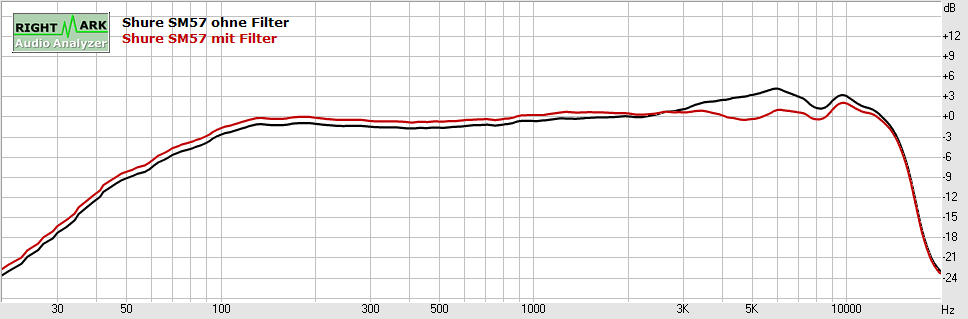
The current issue of Sound & Recording Magazine, Germany, has an article on building a little passive filter that irons out the presence boost in the Shure SM57 and/or SM58. Which I think makes them more versatile and certainly more EQ-friendly.

My article is in German, of course, but the circuit is really simple, so it's not too hard to put together, even if you don't understand the accompanying text.

You can download the complete article from the magazine's website: www.sound-and-recording.de/smfilter

The small print: For your private use only.

Dear German-speaking readers: If you like the article, please buy the magazine. The print media need your support.

SM-Filter57freq.png
 
thanks!!  nice simple circuit . 8) 8) 8) :-* no reason not to put one together and try it. i need a break from troubleshooting my two current non working projects :(
 
Just a few remarks, if you can't read German:

The cap(s) should be polypropylene, I wasn't satisfied with how the polyester ones sounded.

The two inductors are in humbucking configuration. If you experience hum, reverse one of them. If you can't get the inductors specified, you have to factor in their DC resistance. The original inductors are 105R each, if I remember correctly.
 
Thanks for that , I had always wanted to see your ribbon preamp article as well

this filter will be different for shure's modded for no output xfmr ?
 
I have read the article and I have to say I am shocked. Some poor little girl has been traumatised by a man who violated her Hello Kitty tin :D

Cheers

Ian
 
This filter only works as advertized with stock SM57/58 mics. This passive filter works as a frequency dependent load. Taking out the internal tranny lowers the mic's output Z considerably, and I supsect the filter would have very little effect.

No children were harmed or robbed in the making of this project. ;) I saw this Hello Kitty tin somewhere and bought it. It's a pretty box, but the sweets therein were terrible.  :eek:
 
Rossi said:
It's a pretty box, but the sweets therein were terrible.  :eek:

There are only two kinds of sweets--awesome, and absolutely awesome. I am sure my 3-year-old would agree wholeheartedly!

Too bad I don't read German, but the circuit looks neat! Congrats!

Best, M
 
Thanks, Marik! Of course, the circuit itself is very simple - the only little twist being the humbucking double inductors. The real challenge is the precise response mesurement required to adjust the filter values precisely. Obviously, you have to see what's going on if you want to flatten the response curve.

BTW: SM57s seem to be much tighter tolerance than people think. I measured two that I bought about a year apart, and they were petty much identical.
 
Very nice Rossi! Part of my plan for my studio is to have mic panels and preamps dedicated to particular mics with minimal and specific initial processing so any processing you do doesnt begin with corrective measures. And having an sm57 input chain would be among the first i do. Id love to try this and will.

I agree about the quality of the sm57s. They sound really good and consistant at first, but they deteriorate pretty quickley with poor handling and who treats a 57 very nicely? No one!
 
Yes, those are my own measurements at 33 cm distance. I use a method which I developed myself over quite some time.

Quite a few people have PM'd or otherwise asked me about my mic measurement setup, but I'm sorry I can't go into details, as measurements are part of my business. I have to guard some trade secrets in order to keep my competitive edge.
 
Hello GroupDIY.
This is my first post and I registered for this thread.

I can believe this info is not at least as widely spread as the Impedance Gizmo (which is not so spread anyway).
My goal is to make the SM57 more usable in a live situation without a pro Rack EQ unit (which I don't have).

As I understand this small wiring between pin 2 and 3 is forming a resonant frequency around 5K,
which is a CUT peak filter like in an EQ.
The bigger the resistor the less effect the filter has.
No resistance at all creates a huge dip filter in that frequency (or the internal Inductor resistance has effect here).

Rossi, few questions please.
How and why the internal resistance of the inductors is taken into account?
Whats the total series resistance of the circuit should be?
What is the Q factor of this resonance circuit compared to an EQ?
What value Pot instead of resistor will be useful, from Full effect to No effect (is the preamp impedance taken into account).
How to add a passive low-pass filter to it?

I think there is not enough info in English or German.
If could translate the PDF article into English it would be great for the whole audio recording community.

Thank you.
 
Being that some time has gone by , how are you liking it ? has it become standard practice or
have you retro fitted mics ?  I forgot about this but if someone can recommend where to get the inductors
I'd like to try it .
 
All the parts can be found on Ebay.
* Orange Drop capacitor (716).
* 1K Linear Pot.
* 2x 10mH Inductors.

I bought few 10x 10mH inductors and different value caps so I can play with the frequency and Q.

I have built this De-Honker gizmo and it is doing what it should.
I placed the 1k Linear Pot in place of the series resistor so I can have more control of the cut.
There is a sweet spot on the pot depending on the position of the mic on the cabinet and its rather small
around 300 ohm so use a linear pot instead of a fixed resistor.
Also when the pot is on full 1k the sound almost bypassed but you can install a switch to disengage this chain
to return to a normal operation.
It sounds a lot closer to what I hear on the records without using an external EQ or different mic.

I think I'll install another parallel chain from pin 2 to 3 to another troublesome frequency of 7kHz and report.

I will also make some sound clips for comparison on Saturday.

Cheers.
 
Very, very nice. Perhaps I'll get my father to do a translation (he still retains a bit of his German at 93).

A couple of questions: I see a switch for "Low-Z". Might that add a parallel resistor to the network, to bring the overall load impedance down?

Also, there's a switch that selects between the 57 and 58; it seems to add 22nF in parallel with the 47nF cap, for a total of 69nF.

So which position is which? Does the 57 get the 69nF cap, or the 58?

Side note: About 14 years ago I worked on a remastering project for the American folksinger Art Thieme, putting together tapes from about 2 dozen sources. Many of them were recorded in clubs, where they clearly used 57s and 58s; a lot of my remastering work was done flattening those recordings in software, using an inverse curve in the crude EQ of the day (the software was the even-cruder SoundStage, which wan in DOS -- yes, this was a while back!) I wish those club owners had had your loading circuit!

Peace,
Paul
 
Sm57: 20mH + 47nF = 5190Hz Cut.
Sm58: 20mH + 69nF = 4280Hz Cut.

http://www.calctool.org/CALC/eng/electronics/RLC_circuit

My experience with the parallel Resistor across pins 2 and 3 (ala Impedance Geezmo):
It lowers the volume approximately 6db and does NOTHING to the sound.
After long tests (volume matching etc...) With/Without the impedance resistor recording.
VOILA, It sounds the same only lower in volume.
Even the smallest peaks and dips in the digital recorded signal of the SM57 remained the same
(I used the same audio signal to eliminate the human factor).
Don't waste you time.

Rossi's passive filter is WAY my more beneficial than the impedance resistor.
 
Paul , you did an impedance mod article for the 57 , that did make a difference right ?
Don't recall but it made more difference on dynamic mics than condensers ?
 
okgb said:
Paul , you did an impedance mod article for the 57 , that did make a difference right ?

Yes, loading the mic with a total of 500 ohms greatly improved the sound. It worked equally well using a tapped transformer or a parallel resistor.

And by the way, if it's dropping the level by 6dB the loading resistor is too low. Switching from a 2k load to a 500 ohm load should drop the level by aboout 2dB.

Don't recall but it made more difference on dynamic mics than condensers ?

More of a good difference, yes, but only on some mics. The SM57 improved greatly, the AKG 112 tightened up a good deal, most other dynamic mics weren't affected at all.

Some condenser mics, on the other hand, got worse with a lower-Z load; the increased current demand made the head amplifier distort. The SM81 was an example of this behavior.

In short, I think the main mics that benefit from the lower-Z load are the SM57 and the SM58. The difference isn't really a change in frequency response; instead it's the improved damping of the moving mechanism, with lessened overshoot. It knocked out the harshness at the high end that I've always disliked in those mics.

Peace,
Paul
 
pstamler said:
In short, I think the main mics that benefit from the lower-Z load are the SM57 and the SM58. The difference isn't really a change in frequency response; instead it's the improved damping of the moving mechanism, with lessened overshoot. It knocked out the harshness at the high end that I've always disliked in those mics.

For what it's worth, I found it easier to simply replace the SM57 with a Beyer M201TG instead of futzing around with impedance matching networks and loading and such.

OK, so for what the 201 costs, one can buy two and a half SM57s.

I'd still rather have the single 201. But I have two.

:)

-a
 
Back
Top