Flexible Meter, Line Receiver, VU Buffer - With Video of dynamics

GroupDIY Audio Forum

Help Support GroupDIY Audio Forum:

This site may earn a commission from merchant affiliate links, including eBay, Amazon, and others.

bruce0

Well-known member
Joined
Jan 24, 2010
Messages
1,065
Location
Boston
I started putting Bruno's SSL 9K5 (500 series 9K clone) in my rack and while i like them a lot, I started getting worried about power usage. Not so much whether the units are within the API spec, because I have a big honking ClassicAPI transformer and lots of power.  But more that running in Bar mode the LM3915's vary their power usage in Bar mode. the way they are implemented in Bruno's rig, and I worry about how much.

So I did some measurements, the Meter card uses about 93MA off the positive rail with all the lights on and with them off, well, only 17ma. So as the meter wiggles around it is changing the current load by 76 ma.  And I have 4 of them, and I want to put more metering on in addition, and this is quite a bit of variation in sync with the music.

At the top of that range, it is well over 120mA (especially with the relay switches on).

Now I know 1/3 of an amp going on and off with every drum beat is not going to "dim the lights" but I have to believe there is a ground noise effect of all these LED's going on and off.  So I set out to design a new meter. 

I made it with the ability to break off the ends of the card and use it to replace the meter card in Bruno's 9k5 (9k4 too, with some of the card nibbled away, depending upon the transformer ) but also to run as a 16, 32, 48 etc led meter by combining cards in a stack.

It is low enough profile to fit 8 comfortably in 3 slots (I could have more than 16 LED's but I have some plans for the space on the bottom).  Anyway... here is a how I plan to use it.


Attachments

  • meter.jpg
    meter.jpg
    47.5 KB · Views: 269
If Modding is the most sincere form of flattery, this is one mod, to two great DIY projects (The GDIY511 and the 9K5)!

Here is the card installed in a 4k5... You can nibble away the bottom right corner to a pretty large extent to fit a different transformer (This one is an old Altec mixer Transfomer).

It has peak hold but the PCB mount peak hold switch gets broken off to fit into Bruno's preamp.  So here you can see the Normal/Peak hold/Peak reset switch wired in.


Attachments

  • 9k4.jpg
    9k4.jpg
    56.5 KB · Views: 208
Very cool!  I really like the peak hold feature.
I did tests with pulses, and even ran the meters up and down with no signal to see if I could detect (hear) ground noise when I first built these, and found little to none in actual practice, but in theory.........That's another reason you have the bar / dot option.

On my 700 series modules, there is a separate +24V supply to run meters, relays and such.  How about we add two more pins at the top of the 51X spec (52X?) to handle such power requirements?

Best,
Bruno2000
 
Bruno:

Your right, I can't hear it, but I can see the current changes on an oscilloscope.  And I can see the ammeter on my power supply move as music plays, but not on my meter. Dot mode is not my cup of tea, but fixes the current consumption perfectly you are right.

meter.jpg


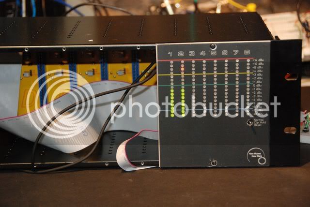
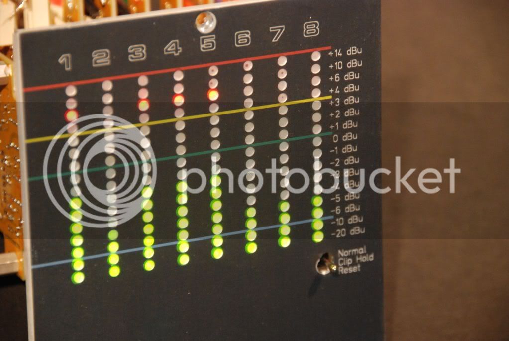
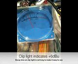
I need metering I can see from across the room on location.  This card does that. Look above it also holds the highest instantaneous level hit (with very fast timing).  I built it with a slot to be able to adjust your card, but it does a lot of other stuff too. 

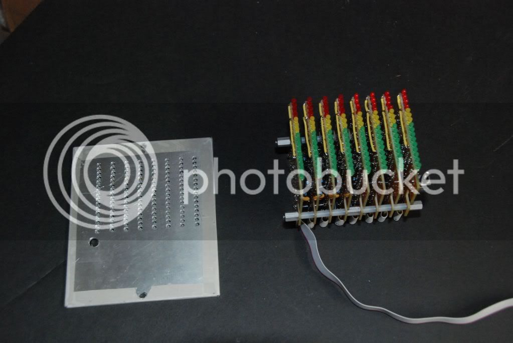
You can arrange an LMXX (For those that are unaware, Th LM3914 is linear, LM3915 is log, and LM3916 is VU) dot mode solves things, but I don't like it, I can't see the dots, and Bar mode can be built up to 10 LED"s in series... which fixes some of the current variation and lowers the current requirements, but I don't think it does 14 LED's and I want a custom scale..

I wanted to use a small amount of current, so I could put them in API modules without blowing the Amperage budget.  I wanted "constant" current, so I could keep the power and ground clean.  I wanted to use inexpensive parts, and I wanted to be able to control the dynamics and the scale and have a lot of resolution.

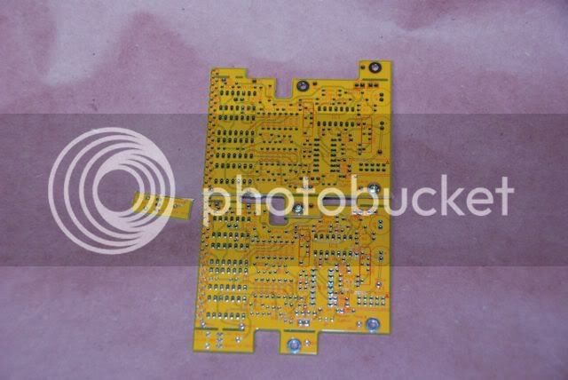
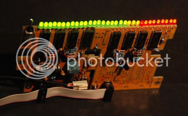
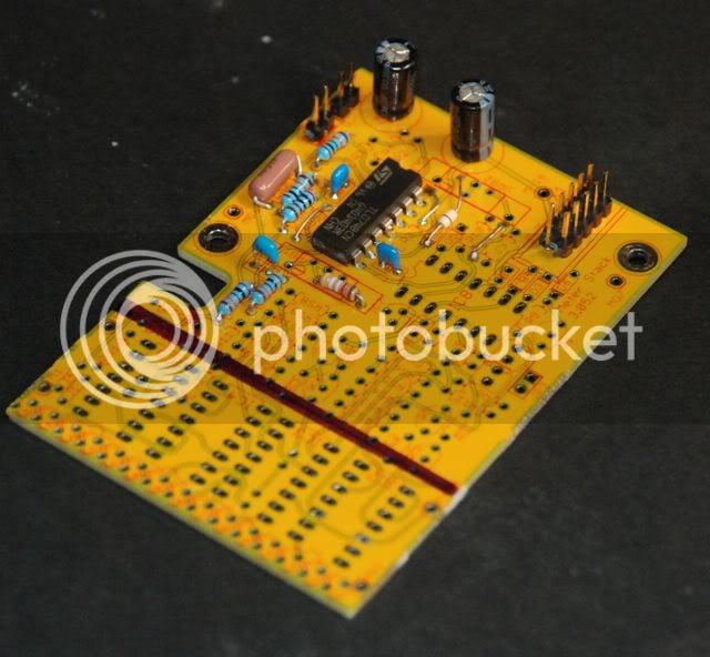
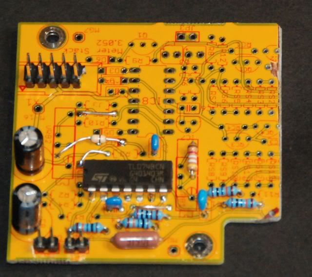
Anyway, I went through a slew of designes and prototypes, borrowing liberally,  on breadboard (I won't blather on about temperature compensating log amps... but I could), and I came up with this, which is a simple series LED meter based upon LM339 comparators, which if you hook up the inputs to a voltage divider ladder, sink up to 16mA of current while they are off... till they switch on (open collector? I think they call it), at which point they stop sinking current and the next light switches on.

It runs in Bar mod with the LED's in series (up to 14 of them work fine on 32 volts) which I run using a 2 transistor current source.
"needs" Dot mode except for power issues.

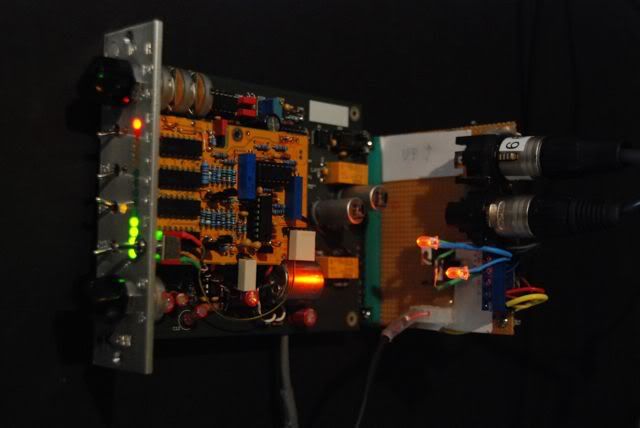
The first section is a balanced input section, using two virtual ground mixers so that the impedance is matched on both signal lines as well as you can match resistors.  This section has adjustable gain.  It is arranged similar to various application notes and is best described in the article by Walt Jung and Adolfo Garcia entitled "Op Amps in Line Driver and Reciever Circuits".  It is not as good as the new, patented InGenious circuit from Mr. Whitlock, but it has a smaller parts count unless you buy the THAT IC he designed.

The following section is a precision rectifier, cloned off some desk meter, also with gain if you change resistances around, which I don't.

The following section is two pairs of two buffers for the upper and lower meter sections, these allow a peak hold capability and seperately configured dynamics for the two region meters.  Upward response is separate from the decay of the meter, each controlled by different resistors one charging and one draining a capacitor for each section.  I keep the "clip hold section" very fast, as fast as I can (no resistor), with slow decay and peak hold, and the lower section of the meter I run with relatively fast rising dynamics and slow decay, which allows it to respond in such a way as to indicate the general level.  I used to have just one clip indicator, but now I have taken to using 3, at 4, 10 and 14 dB, all with clip hold, that way I can tell how close I got to my converters clip (which is 16dB above +4. 

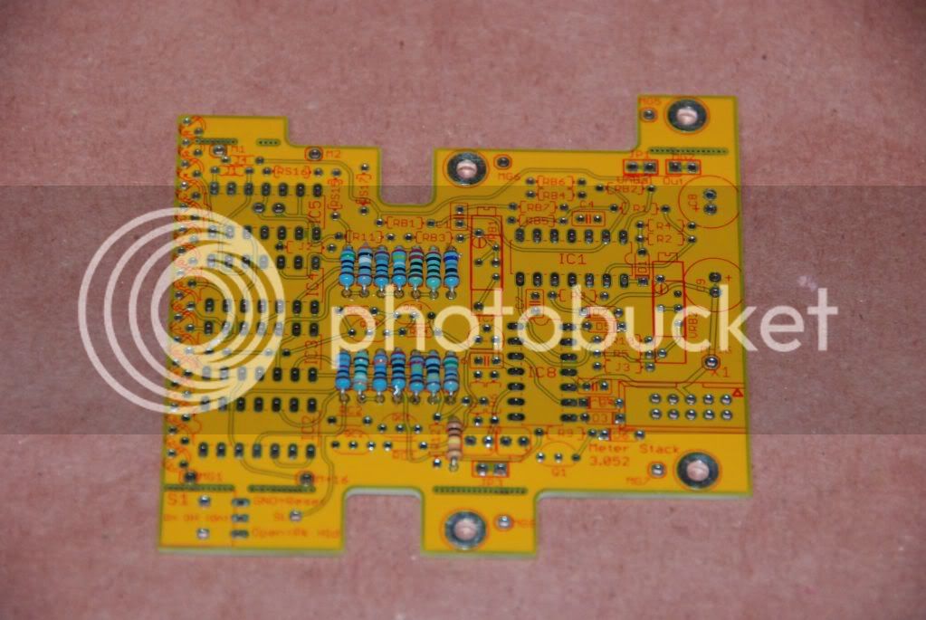
The scale is totally adjustable, using a resistor divider network, I admit it does increase the number of parts quite a bit (there are 17 of them on the small meter).  My scale is set up for VU like with 3 level clip indicators with peak hold and reset.  So -20, -10,-7, -5,-4,-3,-2,-1,0 in green, and 1, 2,3 in yellow, and 4,6,10,14 in red.

Rising and falling dynamics are controlled separately

It runs on +/-16 or more power and depending upon your current source resistor choice it uses 50mA  all the time. Current source using 47 ohms 1 meter uses 50ma, but even less using 56 ohms... lights are still bright (I need to see it in daylight) and I am still trying lower values with it).  I think you could run it on a single power supply, the comparators can handle it, but I have not tried.  if you run 16 LED's with 1 clip light you get a faint dimming of the lower lights when the 15th light goes on due to the voltage drop.  I can't see it if my supply is a solid +/-16.

SingleCard.jpg

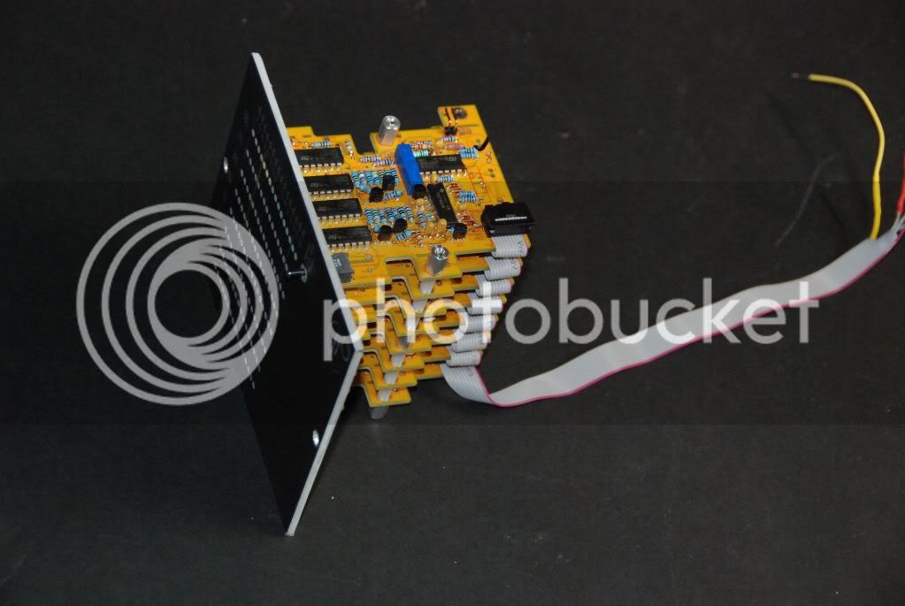
If you break off the tabs on the card, and put in a couple of jumpers, it will replace the board in your (Bruno) 9k5 and 4k5 Preamps (the slot is so you can still adjust the pots on his board).  It will do peak hold too but you need a On, Off, (On) switch panel mounted and it needs to be small, for Normal (on), Peak Hold (off) and Reset((on)).  It converse a larger area of course but uses a lot less power, keeps the preamps within 120mA all the time, and gives me the dynamics that make sense for my converters.

In general, as a single 16 LED meter, you can mount a switch at the bottom that has a On-Off-(On) SPDT pcb mounted switch (I used NKK), middle is peak hold, up is normal and momentary down resets the peak.

StackConfig2.jpg

Stackconfig1.jpg

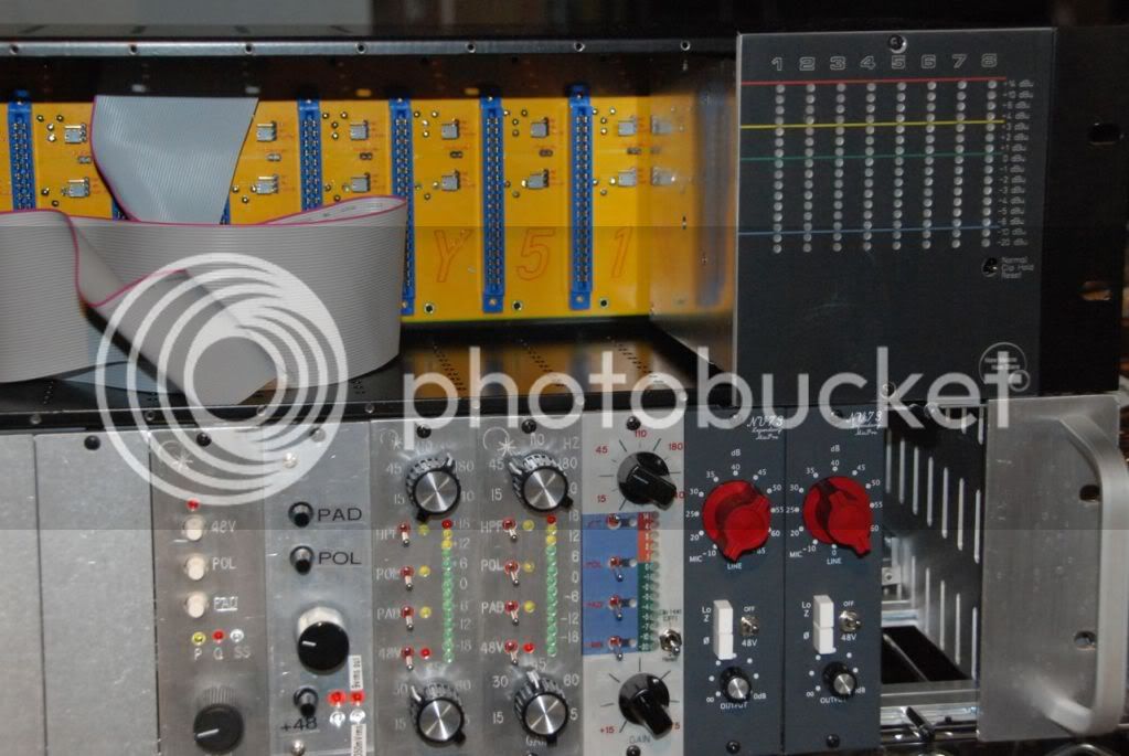
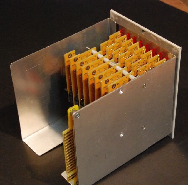
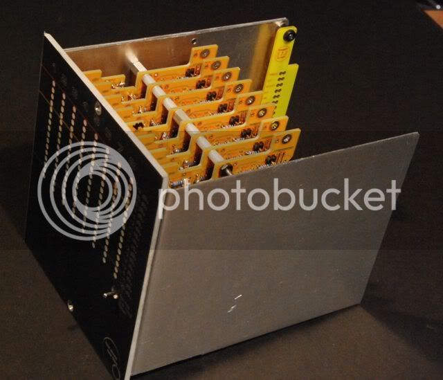
If you bold 2 or more together you can make stacks of them (I am testing out a dual now 32 lights, but I am out of LED's) but I don't believe there is a limit ((except to how much flux you want to breath).

It sits pretty low, and side by side you can space them comfortably with 3/8 inch standoffs... Closer if you want but it will get tight and you might have to do some parts selection or eliminate the trim pots (not really needed)

So I have this meter which will monitor my whole GDIY51x rack (actually, only 8 slots because it uses 3), in my mobile work, and in a lot of home project studio setups, good metering is just gone.  if you are mixing in the box the only meter you get is what is on the converter, which is pretty poor on a lot of boxes.

If you don't build the meter component, you don't need to comparators, and a bunch of parts, and you can still use the balanced to unbalanced converter aspect of the card.  There is an output jack mount for that.

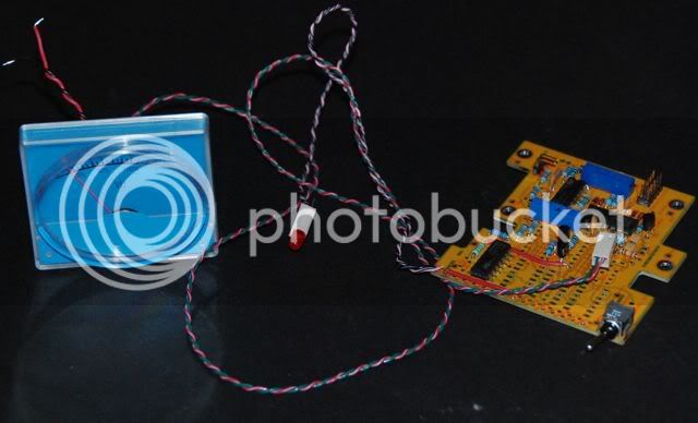
You can have a combination of individual and global resets using the reset line.  The cards connect to one another using a 5 pin connector (but I use 10 pin IDC ribbon to do it because it is easy and available.) The 5 conductors are V+ Gnd V- (ground to reset) and a signal line to link a vertical stack of cards.  There are jacks for input, unbalanced output and signal in.  There is no meter out for analog meters, but you just connect that in place of R11. 

If you build the debalancer, and the rectifier and the peak hold circuits, it will drive a galvanometer (analog meter) and it will do peak hold for you on the analog meter (maintaining the highest level  of meter position using the sample and hold circuit).  I haven't tried this yet, but it should work.  You will also have a second buffer that can drive an LED with a single comparator (for a blinking clip light for instance).

Card is 3.1 inches high by 3.3 inches long intended to be mounted endwise to the front panel (but not necessarily).  If you break off all the tabs it is only 2.3 inches high ( mode... 14 led's no switch). 

Anyway, for me it fills the bill for metering I can see from across the room, but it could work added into many modules or racked equipment.

I gave a lot of thought to the scale I use (which as I say, is set by the resistor divider network, so this is just a personal choice).  It basically has VU scale and Dynamics on the bottom half, but then has 3 very fast response lights on the top that show peak levels (+6 +10 +14) ... and they respond to really short transients... so if the 14 is unlit, I can be pretty sure I didn't clip, but the overall meter works like a VU


Check my cheap temporary front panel.  Printed on clear label material!

This is something I have been planning to try for a while, but I was surprised by how it worked pretty well!

I didnt' make the panel permanent yet because I want to two other capabilities before making a permanent Front Panel Express panel (they charge a lot to drill 128 holes!)  Here is what I want to add, and I have a couple of questions for anyone willing to help.

Channel strip capability:
I want to add a simple "cascade" capability to the meter (in the blank space at the bottom).  This will be a series of 7 buttons or switches, that control Double Pole relays that connect adjacent slots (1->2, 2->3 outputs to inputs).  So I can assemble "channel strips" made of a series of 500 modules (side by side) - Pre EQ Compressor for instance...  I could do this with short cables but cables are expensive and messy.  Interested in any thoughts on this...Do you guys think I need to use relays for this and put them behind the backplane to keep the cabling short, or do you think the 34 inches of IDC cable between each module is ok (it is about about 17 inches of ribbon cable to the front, and back.... the balanced pairs are run side by side in the IDC ribbon, but they are are shielded only by ground wires running along beside them (ground, hot, cold) in the Ribbon.  And they are taped inside the top of the case along the GDIY rack above the modules.  If I put the relay board behind the Backplane I can make the cables a lot shorter (maybe 12 inches total between each module or less if I put the relays on a thin card above the XLR's.  There is not much room there but i could fit those little panasonic relays. I think I need to do the relay approach but it would be easier to do just switches

Summing
And maybe a simple Summing resistor network that could be activated one module output at a time.  Or I may just throw this over and make a full Virtual ground mixer, but if I do that ... I wont be able to have the meters be as big as they are.


Anyway thoughts on that appreciated... but on to the faceplate.

So I made this temporary faceplate.  I drilled the holes in a sheet of aluminum on the drill press (128 holes!... but it went fast enough) using a FPD (front panel designer) template... Then I printed the front panel on a 8 1/2 by 11 sheet of transparent label material (Avery 18665... full uncut label sheets, not glossy) using an ink jet printer (set the printer driver for "Matte Photo".

Anyway, came out clean and simple.  The holes are unprinted and thus clear (other than a bit of sticky tape on the back) and the LED's shine through perfectly.  Any variations in my hole drilling disappear because the light only comes through the unprinted holes , mis-drilled the switch hole so I made it bigger on the aluminum, and fixed it on the FPD template and just punched it with a paper punch.  Looks ok now. 

I don't know how waterproof the ink is, but it seems pretty good.  I think I will try to paint it over with a clear lacquer.  I will let you know how that goes.

I wrapped the tape around the edges of the panel and it is secured extra well by the screws clamping it to the front. Next time I will print the panel slightly oversize so that the edges are black too (you can see the edges are unfinished aluminum color showing through the label.
 
Holger said:
Very nice project...

Thank you Holger, that means a lot coming from you.  The meter you did with the JLM kit was of course nicer... But at some cost in size and price.

I think I can fit 8 in 2 modules, but they would be spaced too tight to read.  8 in 3 modules is very comfortable.  I find 16 lights gives plenty of detail with a proper scale (although I read some early VU spec that called for 32 minimum lights).

This is $12 bucks in parts plus a PCB for a 16 light meter.  Add about $2 bucks for each additional 16 lights.  No limit other than size ( I am testing that out now, I will post pictures).

And I was careful to be able to stack them tight, 3/8" standoffs are fine, I think I can do 1/4" standoffs if I am careful about transistor height, and power connectors.

Peak hold is not as sophisticated as the JLM... (it will leave a particular light or set of lights on if you set it up to do so,  but there is no software ... it is totally analog, so it is sort of simple.

It has brightness control I found (though I had to do a little jumpering on this version of the board to get that to work.)

Oh... and well parts count kind of is bad... lots of resistors
 
Power and reset line connect via ribbon cable.
DSC_0025.jpg


Tight and kind of cute... but you can have them 1/4 inch appart and it still fits.

DSC_0027.jpg


DSC_0019.jpg

Clip hold or normal (slow release so they stay lit longer) operates on the top three lights.

You can have individual clip reset switches for each channel ( you have to have one more diode), but that's a lot of switches, and I can't see it is necessary.

Now on to metalwork for the carrier, and to pick up power from the backplane.
 
Flexible meter/meter buffer/line receiver

I built this generic meter card to have multiple purposes, and I have now tried out most of the possible configurations and it works pretty well. I did have to make some "patches" in most configurations, but for the most part I am very pleased.

Here are some pictures of the tested prototype units I built, and some video of the meter dynamics.

Stacked cards - for larger meters.  I tested 32 lights, but it should work at any height.

The cards are set up to link alternately on top and on bottom.  I should have used some of the unused ribbon connections to carry the 12V reference voltage, and the output signals (thus the manual patches on the back).


Largestacked32lightsormore.jpg


I found that the larger meter needs much less damping to be usable.  This meter is set up in 1 dBu steps from +14 to -15, with the bottom light 5 dBu lower at -20.  Here is video of a very lightly damped meter, no damping at all on the rising signal , and only light damping on the falling signal.  I never damp the rising signal in the Peak Hold section (because I want to catch the shortest peak I can) thus sometimes the meter can "jump" when peak hold is on… but with this setup, it doesn't do that (because the whole meter is undamped for rising signals).

However in the video you can see that the falling dynamics of the top "peak hold" section (8 lights in this case) are slow, to make sure that they are visible, which causes some gapping (near the end of the video I crank levels up so you can see this).

Video


Here is some video of the dynamics of the meter card VU buffer, and comparing a simple active VU buffer.

Galvanometer/Mechanical Meter

GalvanometerVUDriverConfig.jpg


This card can drive a "peak held" meter (which will read the highest peak reached, and hold it until reset), or it can be switched to decay at an adjustable rate.  However in this demonstration what I did was to configure the Peak hold section to operate a peak light, with slow decay, so it is easily visible, at +6dBu.  This in combination with the cheap (chinese?) meter is shown in the video.  For comparison, I also show a video of a common VU buffer (A nice simple bridging design with good performance, but with imprecise balance of impedance to ground on input and with damping performed by a simple capacitor across the meter.).  e

Breadboarding, data sheets other designs showed me that good dynamics required different damping networks for a rising and falling signal.  This requires active components and a simple cap doesn't do it.  This works amazingly well to my eye, and I have included links to a couple of video's of the meter response of a cheap chinese meter, and the same material using a common VU buffer.  In my opinion the performance is better with the more complex setup.  The meter reads closer to average program levels, and doesn't bounce around as much.  While not shown, at low frequency the performance is clearly superior, as the common VU buffer oscillates with the meter (this is probably dependent upon specific meter coil and damping capacitor reactance).

Note that the material here is "broadcast ready" (The Boss) and thus has pretty limited dynamic range, but it gives you the idea.  I need to try it out with raw, uncompressed tracks, to see what's what, but since dynamics are adjustable I think I can make it work.

Video


Balanced line receiver
balancedlinereceiverUNCUT.jpg


Here is the card configured and set up as a balanced line receiver.  Much easier to populated, lots fewer parts, and you can cut it down to 2.3 inches square without a problem.  In this version I populate larger filter caps and a phase compensation filter network.  Each signal line sees a virtual ground (inverting Virtual Earth amp) through matching resistors. I matched resistors with a wheststone bridge and used either 100K or 200K resistors.

The card can be cut down to 2.3 inches x 2.3 inches as shown.

BalancedLineRecievermaybecutdown.jpg


Meter Bridge

I wanted them thin so I could fit a meter bridge in a GDIY511 rack, and this works pretty well.  I think I can make them a little shorter which would help me fit stuff behind them.  In any case, these are 16 light meters, and the dynamics are damped so that the bottom 13 lights look like a VU meter, but the top 3 lights (+6,+10,+14 are instantaneous peak hold lights).  I think this setup will help me know when tracking if I clipped the converters in case I look away for a moment.

MeterBridge.jpg

MeterBridgeProtoBack.jpg

MeterBridgeProtoFront.jpg


Bruno 9K5/4l5 cards

Of course, it works in those preamps, which were my original inspiration to do a modified meter.
4k5meterreplacement.jpg


Some background:


My goal was to have a meter that
1) Bridged a balanced line with little impact on the signal (with high and precisely
balanced impedance to ground)
2) responded well and accurately across the audio spectrum and had dynamics
        adjustable to PPM or VU "like" modes
3) Had a full wave rectifier
4) Would drive Needes and LEDs (a Galvanometer /mechanical meter)
5) Would fit in and replace the meter in the Bruno 9k5/4k5 cards
6) Allowed custom scales - I wanted a scale that showed average levels but alerted me to converter clipping
7) Used low current, and constant current to keep the grounds quiet and fit
        the API spec
8) could make big meters (14, 16, 32, 48, 64 LED meters etc)
9) Had a peak hold capability
10) Was inexpensive, and thin enough to fit 8 in 4.5"

Along the way I found I got some extra capabilities I had not planned for…
1) I could configure just the Balanced line reciever

there were some negatives as well….
1) The prototype board required some patches to get some of the functionality to work.  In fact, all
modes required at least a little modification.  But they were mostly pretty simple.
2) The parts count is high, in particular when building a full LED meter.  But the parts are cheap. 
Most expensive are Switch, lm339's, TL0074's (Digikey has the low offset "B" class in closeout for $0.15 if
you are interested).
3) Of course, it is not a VU meter, which has all sorts of requirements some of which are not really
      relevant today, it attempts to mimic PPM or VU dynamics (depending upon adjustments) but to present
minimal bridging load to the source… to leave it unharmed.

 
Bruno:

What I really want to do is provide mixer functionality in these three bays, along with metering.  But the layout comes out too tight.

There is a schematic, but it has a couple of errors in it.  In my builds I patched the cards, I have an updated one but it is not tested.

There was not much interest I guess, so I built what I needed and have let it drop.  I do have a bunch of prototype cards available, but you might need to patch them.

One issue is the card has several jumpers and cuttable traces to configure it for: 14 LED meter bruno compatible, 16 LED Meter, 32 LED Meter, Analog Meter driver with clip light, Balanced Line receiver, etc.  I have one in my Bruno 4K5 build and will probably add them to my 3 Bruno 9K5 builds.

I am reluctant to post the circuit online due to errors, but will gladly shift some cards at cost, and/or a schematic.  I just don't want to post the schematic because of errors.
 
Sure, there are a couple of little bugs, but I have marked them on the schematic (required me to cut a trace or two and add a strap on the back).  Pretty common LM339 approach adding 1) peak hold, 2) rectifier and 3) separate rising and falling dynamics all using a couple of TL074's. 

Don't trust the comments on the divider network, the values need some adjustment.
 

Attachments

  • stack 3.101 - fix peak hold.pdf
    373.7 KB · Views: 77
I have a bunch of them...in prototype form.  I would be happy to sell them for (updated after I looked at the original invoice) $3.50 each plus shipping (which was my cost).  But you have to cut a trace or two and put a couple of straps on the back ( I can send you pictures of the straps).

I never made a "fixed" PCB... I just modded the ones i used.

Here is a picture of the changes required to the prototype. 3 jumpers (one is hard to see, labeled "strap" in the pic), and 2 trace cuts also marked.  These are only needed if you want peak hold to work properly, without peak hold it needs no straps or cuts.

Mostly cheap parts, except 1 switch. The BOM for a 16 light version with peak hold is pretty much as follows, (if somebody wants to build some, I will put the real list together):

for each card you need...
16 3mm LED's .. I used red green and yellow
2 TL074
4 LM339
1 7812L
4 npn's ( for current source, I used 2N3904 but use what you have)
1 2n5457 (or substitute - peak hold clear switch)
4 .1uf caps
2 tant. caps 1uf caps (rising/falling dynamics timing different values work)
6 1n4148 diodes
1 trimmer for calibration
40 resistors
various 3m style .1" connectors.

Plus you need 1 switch to enable peak hold -  (on)-off-on
momentary "(on)" clears the peak hold, "off" disables peak hold, "on" enables
One switch will clear multiple cards if you are building a meter bridge.


Attachments

  • IMG_1104 trace cuts and straps 2.jpg
    IMG_1104 trace cuts and straps 2.jpg
    201.9 KB · Views: 34
I'm very interested in at least 2. Possibly more depending on if anyone else wants and how many.

Prototype boards have no silkscreen legend? Anything else different?

Thanks man!
 
On the contrary they do have a legend on both sides, legend in red on yellow soldermask.

(That pic is just part of the back of the board ( trace cuts are on the back) but even in that pic you can see some silkscreening) Most of the components are on the front.

The only reasons I call them prototypes is that: (Updated)

1)  they have a problem that requires the patch/trace cut (needed for peak hold as described in a prior post).
2) The PCB mounted switch is about 1/8" or a little more too far back, so the neck of the switch doesn't insert fully into the front panel.  Reaching the switch is no problem however.  It also helps to position the LED's slightly over the board.

The only cards I ever made were the prototype, that is all. But in order to test all the optional configurations (stacked, meter bridge, balanced line receiver, analog meter driver, etc) I needed like 20 cards plus 24 for a Meter bridge so I made 88 of them

I have 30 or 40 extra cards, if you are willing to patch them, just let me know how many you want.  I don't intend to make a "final" run, because I have what I need and there isn't the demand for it.

Here is a picture of the front side of one of the cards, you can see the silkscreen
SingleCard.jpg
 

Latest posts

Back
Top