So I've got these 990s....

GroupDIY Audio Forum

Help Support GroupDIY Audio Forum:

This site may earn a commission from merchant affiliate links, including eBay, Amazon, and others.

dpaton

Well-known member
Joined
Jun 4, 2004
Messages
45
Location
IL, USA, Sol
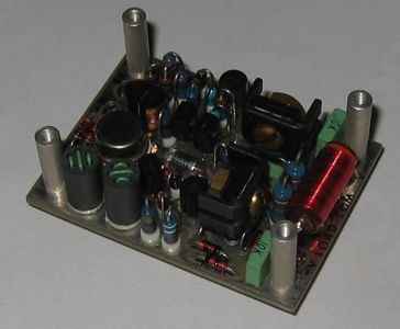
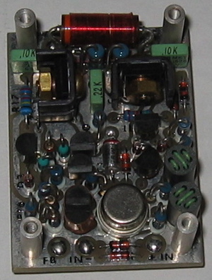
4 of them, which are unpotted and marked with a B. No identifiers other than that. The guy I got them from said they might be early JHs, or original Jensens. I'll post pics later (Monday?) when I get a chance. At $15 each, I couldn't pass them up.

WHat will I do with them? Please allow me a bit of a ramble here.

After doing a complete scouring of the Google results and the various and sundry META threads, I'm still at something of a loss as to what to do with them. I'd love to find a way to integrate them into my (always-being-redesigned) 8ch 1U mic pre, either as a pair of dual-990 preamps, or four single-990 preamps. The Jensen twin-servo concept is nifty, but the dual section reverse-log pot is a bear to find. Plus, I like the idea of 4 preamps, not just 2. Maybe one twin-servo and a pair of singles? There aren't many circuits I've found that look like they'll fit in 1U without a major redesign. The SCA J99 perhaps, with relocated front panel controls. Maybe one of JHs preamp schematics from the 990 app note? I'm feeling a little lost on all this right now. I know at least 4ch of the box will be based on Kev's mic pre (SSM2017/2142), but beyond that it's all up in the air. Really.

I keep thinking that a pair of the Jensen twin-servos would be really cool for the direct-to-stereo stuff I do from time to time, but I want these 990s in my recording rack too. Hmm. Decisions, decisions.

I'll get those pictures soon, I promise.

Thanks all.

-dave
 
unpotted?!!?? What you do with them is trace the layout and post it for those of us who could never get our layouts working!

kent
 
[quote author="kent"]trace the layout and post it for those of us who could never get our layouts working![/quote]

What layout are you using? Did you thermo-couple the output transistors to their bias diodes?

Somebody here already has a working layout for these, IIRC.

Peace,
Al.
 
If they use the same pin out as an API then they're JH, if they're a bigger open platform with circuitry accessable then they're Jensen built. I believe the B's were a early JH version that only handles 18V(vers. C goes upto 24V or any votage above 15V I believe) Call John Hardy he'll have the whole truth.
 
They are indeed open and unpotted, with the can-style LM394 and a pair of TO92s wrapped in a copper curl, with a little thermal grease nearby (Q3/Q10?). There is no trim pin, but it otherwise matches the 990 pinout I've seen elsewhere. Like I said, I'll post a pic when I get a chance, definitely by Monday. I'll be checking with JH about the specs, assuming it's one of his. It has all the pins to be, but it doesn't look like it's quite the right form factor. If it really is one of his, I might be able to change R10/11 as mentioned in his datasheet to make it +/-24V compatible. I love headroom :cool:

NYD-
Unfortunately, I don't have much of a use for another 2-bus (I assume you mean one that's buffered with passive summing?). I've got one built around hybrid opamps already, that handles the group ->LR summing on my board. Tascam didn't do it very well originally on the 2600mkII :roll:
I'll happily entertain any schematics you want to share however :grin: Watching the passive summing thread a while back was quite educational.

A pair of amazing mic preamps, or 4 almost-as-amazing pres, depending on the topology, is much more appealing to me. I need some color and character to compliment the stratghtwirewithlotsagain preamps I built in college. I've also been toying with making them into a DI, but that seems very selfish, since I don't play bass well or often enough to justify it to myself.

Kent-
I'm pretty sure that's already been done. My recollection is fuzzy, but I know I ran across it last night while madly clicking thru the posts here.

Rich-
The only reason I have to doubt they're JH 990s is that I can't find any record of John making a B version. Maybe he'll jump in here over the weekend and drop some knowledge here (hint hint hint). I'll post a pic as soon as I can.

This sure is shaping up to be a whole lot of fun. I'm glad I have a good distraction to keep my mind off of work this afternoon. It'd really be dragging otherwise. It's actually sunny outside today :!:

-dave
 
I do not think John Hardy would mind if you gave him a call. He seems to be pretty willing to offer knowledge where he can, and he might get a kick out of it if they truly are some of his older deisgns.

I would think Jensen dual servo and nothing else. My 2 Jensen dual designs are one of my favorite preamp pairs. I am using Tim Ryan's J99 boards, which currently use a Lundahl 1538xl on input and a Cinemag on output and they sound freakin amazing.

Shane
 
They may not be John Hardy's parts. When Deane Jensen released the 990 design, there were a few companies making the 990. Pacific Recorders made them for their broadcast mixers, and Boulder made preamps and power amps using that part. Maybe the "B" is for Boulder.

Regards,

Vince Poulos
Speck Electronics
 
[quote author="dpaton"]but the dual section reverse-log pot is a bear to find.[/quote]Nope, not so hard...

On JH's pricelist in the 990 section at the end. USD$19.95 each.

Optionally, You can get 10k dual RLT detented pots from Joe Malone for USD$10 each.

I have in mind to get some of Joe's PCBs and a couple of JH990 and build a dual servo mic pre with Cinemags... Someday!

HTH!
Charlie
 
As promised, pictures. Note the R15/L3 combo which IS in series with the "load" pin, and the Q3/Q10 pair that's thermally coupled. Q10 is configured as a matched diode, just like in the JH990 schematic. Yes, I know the lighting sucks. My camera is having issues. Any and all input is welcome.

-dave

IMG_0757.jpg


IMG_0758.jpg


IMG_0759.jpg


IMG_0760.jpg


IMG_0761.jpg
 
Looks like the Jensen version.
Hey, get some input transfromers and build up some mind-blowing mic pres! :green:
 
I dropped JH a note...I sure hope he got a chance to enjoy the weather we had today. 50F in February is pretty rare in northern Illinois.

I'm actually thinking of grabbing some transformers and making a pair of the "Famous Jensen Twin-Servo(r) Basic Mic Preamp Circuit". I'll need to save up for the $416.36 (plus tax and shipping) in transformers I'll need tho. Ouch!

That would be killer. Now if only I had a schematic for a truly killer 16/48 ADC so I could jack it right into my DAP1...

-dave
 
What is the pin labeled FB? i have never seen that before.

Those things look awesome! Not only does everything fit, but it's all straight and neat. Potting them, unless necessary for heat performance, would have been a shame! ...to cover up all that nice work!

Shane
 
Category5-

Check out the schematic linked in my post above, as well as page 3 of this PDF from JH's site.

The FB pin is connected to the junction of the final transistors, before the RL isolator and the LOAD pin. It's there to provide a direct connection for compensation capacitors and the feedback resistors for gain setting. If you connect those components after the RL network, it'll have a pronounced effect on the transfer curve. The inductance will act like a low pass filter. For a mic preamp with amazing transient response, that's not something you generally want.

-dave

Edited for clarity and corrections
 
Does anyone have an EAGLE layout for the pins? Or maybe a nicely dimensioned drawing of the spacing so that I can design the motherboard for these guys using the Mill-Max pins? I'd hate to try it with my wonky wooden ruler and get it just wrong enough that the pins bend when try and insert the module...

-dave
 
OK, I did not read the whole thread. But, I think the 990 in the picture was made by Steve Hogan, formerly of Jensen Transformers. His own company is known as "The Sound Steward", so the "TSS" would probably be that. I'll advise him of this thread.

I'll actually READ this thread later to find out what I SHOULD have said.

John Hardy
The John Hardy Co.
www.johnhardyco.com
 
Steve's 990 modules include what is know as an "Output Isolator", the big resistor with a coil wound on the body of the resistor. This is included in the Jensen 990 schematic, but it is not normally part of a generic op-amp. The "FB" pin is the "feedback" pin. This is the actual output of the 990. One end of the Output Isolator is connected there. The other end of the Output Isolator is the "Load" pin.

You will often find a low-value resistor in series with the output of an op-amp in case a long cable is connected to the output of the op-amp. This isolates the cable capacitance from the output terminal of the op-amp. Without this isolation, the cable capacitance could shunt the feedback signal to ground (the capacitance is between the signal conductor of the cable and the shield, or ground), resulting in insufficient feedback at high frequencies. Ultimate result: oscillation of the op-amp. But a simple resistor causes the output impedance to be higher than necessary at ALL frequencies, not just the ultra high frequencies where the cable capacitance could be a problem.

So, Deane Jensen came up with a resistor/inductor combination as used in power amps. After all, the 990 is practically a small power amp, capable of >2 watts of output. The 3.6uH inductor provides essentially a zero-ohm impedance from DC to a couple-hundred KHz or so. The impedance of the inductor eventuall rises to the point where it is much greater than the 39.2 ohm resistor. So, the output impedance is zero-ohms in the audio bandwidth for maximum signal transfer, and 39.2 ohms above 200kHz or so, for isolation of cable capacitance. Here is the Jensen pdf for the Output Isolator, including a frequency response plot:

http://www.jensentransformers.com/datashts/oli3.pdf

John Hardy
The John Hardy Co.
www.johnhardyco.com
 
John Hardy advised me to take a look at this discussion. The 990 modules in question are TSS-990-B modules made by me and formerly sold by Jensen Transformers and now sold by me directly. The TSS stands for my company "The Sound Steward". The "B" design was done by me when I worked at Jensen and has a number of improvements to the original 990 circuit -- mostly improvements in the DC biasing. Deane's original circuit had two resistors which were selected for different voltages. The 990 B has a temperature-compensated current source that feeds the other 2 current sources so that the "B" can operate from Bipolar 12 Volts to Bipolar 24 with no change in components. The "B" version is very similar to the current "C" model with exception that the "C" has much lower input offset voltage (<100uV, <25 typical) than the "B" (unspecified but usually around 600 to 1000uV). That's why the "C" works better in the twin servo circuit than a "B".

By the way, I believe it is still possible to obtaiin the 1K dual reverse log taper pots from Jensen, but if I were doing a no-compromise mic pre I would probably use high quality resistors and a stepped switch.

Thank you for the compliments on the cosmetics and layout. There are quite a few graded and selected parts on this module. I have several different test fixtures that help me sort out the right part to solder in.

The pins are assembled with a jig that holds them exactly in position while they are being soldered so that they will fit perfectly in a pcb.

I have a layout sheet with the dimensions of the pin layout and I stock the mating sockets. Contact me for details.
 
> Yes, I know the lighting sucks.

There's detail in there, I've boosted it some:
TSS990.jpg

ETHAN: Why is this 304-wide image triggering the forum re-size mechanism?

That's a pretty thing. Tightly packed. Any good fool can copy the 990, but someone took great care with this one.

> What is the pin labeled FB? i have never seen that before.

You find it on various amps for various reasons. Some of the old audio amps had sloppy DC performance. Even with DC feedback they could have tenth-volt DC error at the output. If that feeds a fader or a transformer, it makes trouble. So they gave you a direct "FB" output, and another "OUT" output on the far side of a 50uFd DC-block capacitor. You (almost) always took the feedback from the FB pin, but usually took signal from the cap-coupled DC-free pin. (If you needed a direct cap-less output, you took it from the FB pin.)

If you cap-bypass the feedback loop on a Jensen 990, the DC error is very low, at least by 1980s standards, and an output DC-block cap is not always needed. (It may be a good idea, but current fashion is a 0.05uFd cap on a TL081 chip servoing the 990, instead of 47uFd of damp aluminum.)

> an "Output Isolator", the big resistor with a coil wound on the body of the resistor.

Good explanation.

That caught my eye, because AFAIK Jensen likes to sell the isolator separately. It is not needed in all applications, and isn't basic to the opamp function. So I doubted this module was made by Jensen. I suppose Steve felt it was generally worth having, and inexpensive enough to throw-in on every module. Again if you are sure you don't need it, take output from the FB pin. (Or better: now that Steve has visited, ask his advice.)

> The "B" version is very similar to the current "C"

If I may reconstruct history for the young guys who missed it: in the late 1970s when the 990 was gelling, transistors cost money. And the 990's simplicity only works with pretty good transistors. The cost of the silicon was high; transistor count was kept low. So the original was resistor-biased and sold in several versions for the several common supply voltages. Later, good transistors got more affordable, and some "obvious" (not trivial to detail-design) changes were made: constant bias over large supply range, and I think the current-mirror in the first stage was added or improved. I love the fact that the basic design is older than many of its users, is still the Gold Standard of fine audio, and there has been no big change, just adaptations to better parts at better prices.
 

Latest posts

Back
Top