1176 seems to work ... Pics

GroupDIY Audio Forum

Help Support GroupDIY Audio Forum:

This site may earn a commission from merchant affiliate links, including eBay, Amazon, and others.

ChuckD

Well-known member
Joined
Jun 3, 2004
Messages
578
Location
Irvine California USA
5.jpg

8.jpg

6.jpg

7.jpg


*****The Hum as I mentioned before is at -47.3 dB... Not sure if that is considered good or not... ****

Let me know if you think I should try to isolate the ground loops or just live with it.

I think I am done with compressors!! SSL / dual Fopto / dual 1176.
I might take on another Pultec now that the heat problem is solved!

Then on to 2 108i's.... If I can get some money for switches.

-ChuckD


[/img]
 
Hum can come from many, many places.

Carefully read all the hum-hunting threads around here, and you will get an idea of where to look.

Don't expect it to be a simple text-book solution.

Jakob E.
 
Nice Rack of Gear!! :grin: :grin:
1) Is the Hum in both Channels?
2)Right side has output control (POT) wires going past toroid xformer. Shield of this may be picking it up to ground plain. Or is that (3) different wires? for the pot. Pretty close to a xformer for a ground wire.
3)Output xformer of course no cans ($20.00 fix) and power mains go right to front of faceplate over top of right channel.
4)24-0-24V power over top of output xformer.
5) Move the toroidal xformer as far away and rotate it to find the least amount of hum. I used the VU on my mixer with no signal and the preamp cranked up.Your ears will get you within a dB. I turned it around and noticed about 5dB difference Lowest to Highest. I marked the null or lowest side with a sharpie marker.
6) Make all of your power leads as far away from board as you can.Never crossing.
7) Damned nice rack!! :grin: :grin:
 
[quote author="StrayCat"]Nice Rack of Gear!! :grin: :grin:
3)Output xformer of course no cans ($20.00 fix) and power mains go right to front of faceplate over top of right channel.
[/quote]

Where do you get the cans for the OEP transformers? I couldn't find them listed in the Newark online catalog.

Also, when using the OEP transformers with the gyraf layout, is the wiring different? I know that they don't physically match the layout on the board, but does the pinout match up between the Lundahl and the OEPs?

Thanks,
--
Don
 
A nice collection of DIY!

Just a few thoughts on getting the hum lower...

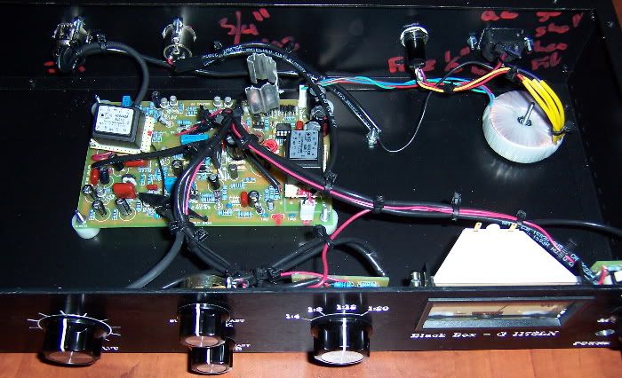
Have you wired the output transformer as 1:2? This naturally brings the noisefloor up +6dB. I found that wiring a strap of thick wire diagonally across the board from the 0V input point to the ground point across the board helped a bit (unless this is one of mnats boards, where I think he broke the loop with a bit of reworking of the ground traces...)

Also, is the power switch on the front panel switching the mains supply? From the pic it looks like the mains leads pass directly over the top of one channel- and near to the "link" wires (which are high impedance paths and should be well screened to prevent modulating the gate of the FET with external signals!) Check and double check all your screens and cabling. Use "sliding shields" where you only connect one end of a screen to 0V, and arrange multiple screens (e.g. the path from main board, to a pot, and back again) with the screens linked in the middle but only at one end.

Great DIY work though!

Mark
 
Nice! :thumb: I may follow your lead and build my Dual 1176 just using the onboard power supplies. Is that an amveco 22v-0-22v? If so, which VA and if not, which one is it?

Thanks
 
WOO HOO!!! I just finished mine today as well. I haven't calibrated it yet, but everything seems to work as it should on the first time out. The meter definitely isn't tracking correctly, but I'm assuming the calibration will take care of it.

I just want to say that I used the OEP transformers on the input and output, I did NOT use the cans, and I have ZERO hum. I can't hear any at all. I have not wired up the power switch yet, and may just leave it without the power switch. I turn all of my equipment on and off at my power strip anyway...and if it might induce extra noise...I don't need it.
 
Great Thanks TubeJay!
Looks nice.

Can you do one more thing for me? Just trace, write back with the order of the AC GND to GND etc... connections.

I want to copy your GND connections as I think that is my main problem.

Thanks

-ChuckD
 
I've got three connections to ground.

1. From the AC receptical to the Chassis.
2. From the Input XLR pin 1 to chassis and to the ground plane of the PCB/and transformer screen.
3. From the Ouput XLR pin 1 to Chassis and to the ground plane of the PCB/transformer screen.

So it goes:

PCB ground plane > XLR pin1 > chassis

You can see the big nut in the middle with the ground wires attached to it. There the three wires I mentioned above attached to it.

My plan was that if there was still hum with this setup, then I would cut one of the grounds to the PCB and connect the input/output grounds together, which is what I did with the GSSL. This worked though, with no hum, so I'm leaving it!

Let me know if you need any more info, or my answer was too messed up!

:green:
 
Back
Top