Wiring the Lorlin for Green Pres

GroupDIY Audio Forum

Help Support GroupDIY Audio Forum:

This site may earn a commission from merchant affiliate links, including eBay, Amazon, and others.

matta

Well-known member
Joined
Jan 11, 2005
Messages
1,640
Location
Cape Town, South Africa
Hey Guys,

I am now adding the Lorlin's to my Greens and will then be wiring up
the audio connections and hopefully they work!

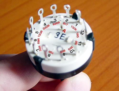
I have the Gain switch layout from Peter and he has named the 12 poles 'a' through 'l', I assume these are 1 to 12
as indicated on the Lorlin I have below.

I have seen Kev's switch (below) and it is a great help, but I just want to check with those of you
who have built them before I start soldering.

lorlin01.jpg


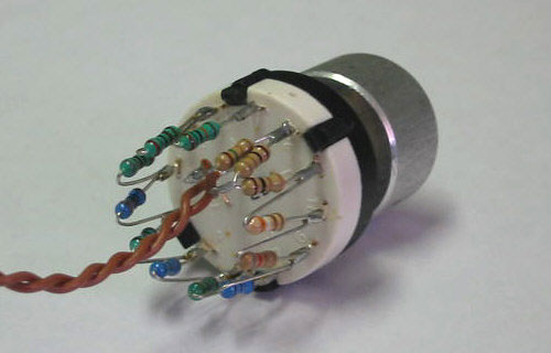
Below is the switch I have, I have marked and the values of the resistors
below the poles, is my thinking correct.

lorlin02.jpg


Then on Kev's it looks like the 1R5 goes to the center pole (A). Where do you then attached the
2 wires that go to the 2 pole on the board.

Thanks in advance.

Cheers

Matt
 
Hey Dust Artist,

They are actually prototypes, version 9 and 10,which I got from Peter, just before V14, though I assume the switches are the same.

Thanks

Matt
 
If you look at the cct here :

http://1176neve.tripod.com/id10.html

the rotary switch points are wired a - l. These points correspond to pins 1 -12 on the rotary switch. So between pins 1 & 2 (a & b on the cct), you wire the 150k resistor. Between pins 2 & 3 (b & c) you wire the 2k7 resistor, and so on.

The 1R5 is effectively "floating", one side connected to the rotary (pin 12), the other to the wire that goes to the Molex. The other Molex wire will then go to the centre pin.

Not sure it was wired to take in the centre pole.

Peter
 
Thanks Peter,

That was that cct that I was referring to, it all made sense. I just wanted to check I was right, everything was expect the fact that 1R5 is floating, which makes complete sense now!

Does it matter which Molex wire goes to center pin and the other the 1R5 floating resistor?

Thanks

Matt
 
Peter,

Thanks again, I am such a Newbie! Having looked at the cct I think I see which one goes where. I guess I wanted to check that I couldn't get it wrong... but if I did I guess it would be an easy fix.

Thanks

Matt
 
Will someone clairify something for me.
It looks in the picture like there are two 2R resistors soldered together between pins 11 and 12. (the schem only calls for one) am i seeing this wrong.

Also does the center post on the switch get used.

Thanks
Ryan
 
[quote author="Ptownkid"]to a wire of your two the come from the board,
Cheers[/quote]

That sentence got de-railed i think?
You still answered half of it, but are there two 2R resistors there or just one?
 
looks like two ONE ohm resistors to me. This is DIY build with what you have.
 
Yeah as Gus said, DIY with what you have. I ended up using 2 2R on mine,
where I should have used a 1R5 I used a 2, so both 11 and 12 pins were 2R.

If you read through my posts you might see I had a serious issue with
under gaining on my pres, turns out all my 1R5 resistors were 15R!

So I had to use a 2R, but it works fine, the difference will be negligible I
think.

Cheers

Matt
 
Thanks everyone!
I wired the rest of the switch, i just held off on that part because the picture threw me off a little.

Ryan
:guinness:
 
[quote author="Gus"]looks like two ONE ohm resistors to me. This is DIY build with what you have.[/quote]

yeah thanks Gus

... or what you can buy
2 ohms is not in the JAYCAR catalog
this has been pointed out before

Gswitch01.jpg

here is the other half of the picture and I think you can see the two resitors in series
this is the best my camera can do :sad:
and there are words of explaination on a couple of sites and forum threads ... in a number of languages so I'm told

Do
It
Yourself

no offense meant ... we do try to help as much as we can and both Pete and I answer many, many emails
if the web pages don't help we could remove them
 
I'm about to connect my lorin to the PCB.
I was just wondering if it mattered which wire went where.

like the wire from the center on lorin needs to go to the bottom pin?

Cheers
 
[quote author="rpd"]I'm about to connect my lorin to the PCB.
I was just wondering if it mattered which wire went where.

like the wire from the center on lorin needs to go to the bottom pin?

Cheers[/quote]

You mean whether you connect it A - B or just the other way around ?

It doesn't matter.

Not sure if it was in this thread but the question & answer are out there.
 
Back
Top