JCN1218
Well-known member
Hi everyone,
I'm currently working on a stereo 1176, but I'm running into all sorts of problems right at the finish line. I'm trying to get one working channel and it seems like I'm pretty close to achieving just that. Unfortunately I'm having a problem with my T-Pad attenuator.
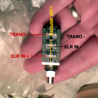
This is the attenuator in question: http://www.hairballaudio.com/catalog/parts-store/attenuators/bi-600-t-pad-attenuator
I have one wired up for each channel at the moment. On channel 2, the one that's closer to working, I'm noticing some odd behavior. The volume spikes dramatically within the first 1/4 of the attenuator's rotation. I hooked it up to my DMM and while turning it slowly I saw the VAC start at around 0.02, but once it hit 0.03 it quickly spiked up to 0.1 VAC. For a very short portion of the rotation, VAC would drop from 0.1 to about 0.8 before returning to 0.04. This doesn't seem like normal behavior to me, and it's preventing me from continuing with the calibration process. Is this attenuator busted, or is there a problem elsewhere? Keep in mind that I'm measuring my values directly from the output of the attenuator, so before the input transformer. Could the cable's proximity to the main power wires be causing this?
I'm currently working on a stereo 1176, but I'm running into all sorts of problems right at the finish line. I'm trying to get one working channel and it seems like I'm pretty close to achieving just that. Unfortunately I'm having a problem with my T-Pad attenuator.
This is the attenuator in question: http://www.hairballaudio.com/catalog/parts-store/attenuators/bi-600-t-pad-attenuator
I have one wired up for each channel at the moment. On channel 2, the one that's closer to working, I'm noticing some odd behavior. The volume spikes dramatically within the first 1/4 of the attenuator's rotation. I hooked it up to my DMM and while turning it slowly I saw the VAC start at around 0.02, but once it hit 0.03 it quickly spiked up to 0.1 VAC. For a very short portion of the rotation, VAC would drop from 0.1 to about 0.8 before returning to 0.04. This doesn't seem like normal behavior to me, and it's preventing me from continuing with the calibration process. Is this attenuator busted, or is there a problem elsewhere? Keep in mind that I'm measuring my values directly from the output of the attenuator, so before the input transformer. Could the cable's proximity to the main power wires be causing this?