It's Alive!!! diy81

GroupDIY Audio Forum

Help Support GroupDIY Audio Forum:

This site may earn a commission from merchant affiliate links, including eBay, Amazon, and others.

fuzzbox

Well-known member
Joined
Jun 4, 2004
Messages
95
Location
Montreal, Canada
Well it's been a very long ride but it's coming to an end.
IMG_4180.jpg


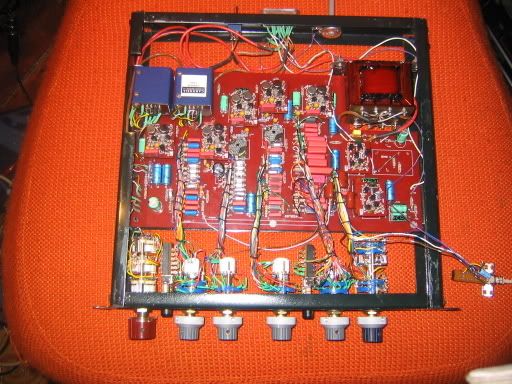
I got the pre, filter, Eq working.
I'm still having trouble with the output amp. (ran out of diodes and transistors) they kept blowing up, and I don't have anything to check
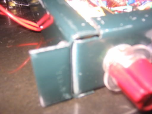
which ones are good. I also damaged one of my low mid inductors,
it didn't have a dot and in haste I put it in backwards, damaged when I took it out.
so if someone can point me in the right dircertion to get a new one I'd apreciate it.

IMG_4179.jpg


I'll update some of the files for switches as I've found some problems with
the TT files.

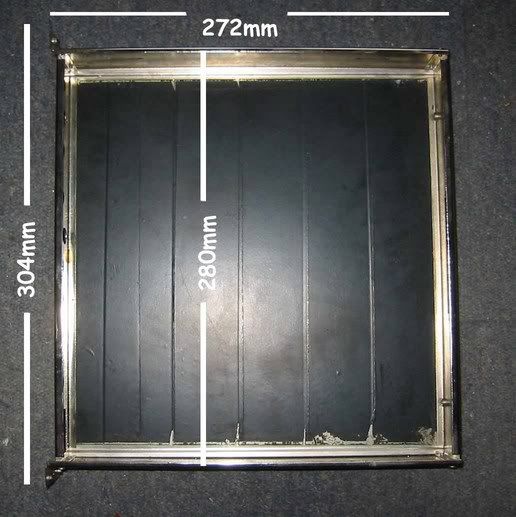
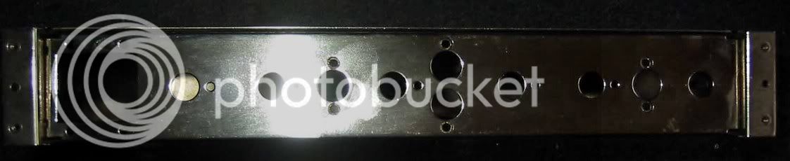
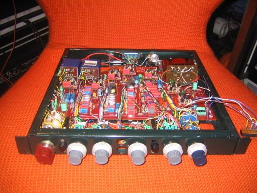
Now to find a case and faceplate, then put these suckers in a box.
 
Excellent! Great news. Congrats. :guinness:

About inductors, some guys have been selling their iron, maybe someone can offer theirs here. You can always order more from the source, but we'd want to get a small group order of 10 pieces or so, otherwise they are pricey.

Sorry you're having output amp troubles. Sounds like a voltage is reversed or something. I have a 340 schematic if you need one.

How many hours would you say it's taken for construction, not counting troubleshooting?

How did you afix your inputs?

Curious about the switches.

Well done.
 
Hey man, glad to see that you are in the final stages of your 1081.

I am waiting for the last parts for my 2 GSSLs but will not start on those until I finish my LA2A project.

We'll have to get together again after I finish them.


The 1081 looks great!

jim
 
smily698.gif

Congratulations! You're the first one, eh? The Winner! :green:
Maybe you can confirm the component placement pdf? http://www.nrgrecording.de/html/neve1081.html

Ohohh... the low mid inductor. :cry: Is the core broken or one of the pins? Unfortunately the inductors are not pin compatible with the siemens/epcos ones and the vtb9047/vt22674 is the one with the highest mH value. (maximum is 5,11H i think) Thats much for such a small core i think. Hard to do at home.. with a N48core maybe 1787 windings. I could try to do one but iam curious about if it will work or if I ran out of space with a 0,1mm wire.

What about Phase and Phantom Switches?

Frank.
 
Thanks for the feedback guys.

Frank I didn't win yet :oops: it's not 100% done, still got that nasty output thingy to workout. and pfffff phase/phantom.......hey I put together a 1081..........now I just have to figure out what it does exactly. :green:
I'll have time tomorrow to check all the files.

Tommy I would say 200hrs+ those amp blocks are hard on the eyes.
and what you mean by afix the inputs.
I got the tommytones schematic and the one from the user guide, is yours different?
 
I meant, how did you mount the input iron?

Just checked, and my 340 schem is the same as in the user guide. Did you ever compare that with Tommytone's?
 
Nice Work FuzzBox ! Very inspiring.

Hope you can get the output amp issue sorted out soon.

What were some of the harder parts to find (ie: transistors etc.) and where did you source them (Other than the group buy Iron etc.)

Anything you would like to share would useful. :wink:

Good Job !

:guinness: :sam: z
 
[quote author="fuzzbox"]I'm still having trouble with the output amp. (ran out of diodes and transistors) they kept blowing up, and I don't have anything to check which ones are good.[/quote]

from John Kletts Website:
"The BA240 and BA340 amplifiers have a small variable resistor on them to set the bias. At one end the distortion is high and the amplifier gets hot - the range of the bias adjustment can make the output transistors both turn on too far and this will cause a meltdown. At the other end the distortion is high but the amplifier stays cool running in Class B. Starting with the adjustment at the class B end of the range and running with the output at +20dBv I gradually move the bias adjustment and watch the distortion drop. There is a point where the distortion stops falling. This is where I leave it - going any further will not reduce distortion and will push the amplifier too close to thermal overload. This adjustment must be done with a heat sink on the module. Operating the BA440 amplifier with its heat sink off will result in a melt down."

I can't confirm that yet because I have a 440 amp but you could check the following:

10µ/25V polarity wrong
22µ/16v polarity wrong
100k resistors at the ouput of the bipolars is wrong - must be 1R5
4K7 has to be 47K
4K7 has to be 47K
3K6 has to be 36K
BC441s (output transistors must be cooled) you can use BD139 and BD140 (but check the pinout [its different] )

I dunno, maybe it helps? Good luck!
 
Hi Fuzzbox,

Where did you get your module frame? Is it the same dimensions as the original? I have two of these to do and I'm thinking of starting a group order for these to have modules cases/frames made up and then also racks to put them in. I'm very curious as to whether or not these will fit in an original sized 1081 case with the new PCBs and transformers and all. If we can get a proper size together, I could likely get it all up and running at once and hopefully help some people out and also help get a rack for you if you wish. I know the originals were 12 inches long, but I don't know how deep they were and if that depth will work on this project.

Anyone out there have suggestions?
 
I just emailed Frank with all the info on the switches, and a couple of little things on the main board. He has a way of making this stuff look easy to do, which is great since honestly it's all paint by numbers for me.

The hardest parts to find were the diodes, aa144/bax13.
I got them at
http://www.nikko-electronics.net/catalogue/product_details.php?id=7523

also the pots which I got from the good folks at Pheonix audio. ( cost way more than I want to admit to my wife)
I had to modify the switches a bit to get the pots to fit, I shortened the spacers, and on the treble and bass switches the buttons just barely make a connection.

The rest you can get from Farnell/ mouser.
To my Surprise it cost less to ship from England to Canada and faster
then from Mouser in the States. that includes duties and brokerage.

The case I made myself out of metal I found at Home depot, it was amoung the metal 2/4 stuff.
I got a photo from peter of the case along with a pic of the face.
just copied it the best I could, jig saw, dremel, hand drill.
case.jpg

fp.jpg

Tillman If you could get a group order for some I'd be very interested.
wish i could get a faceplate.

Thanks Frank, I'm just waiting to get some more transistors.
 
sorry - can I have some more info on the metal work - did the panels come with the lip - or did you cut to size - then fold the metal?
 
uK03878

Here's the metal I used.
IMG_4211.jpg


It came with the lip. I used self tapping screws to put it all together.
IMG_4206.jpg

Not as pretty when looking up close. Thats what you get when you use a visegrip.
IMG_4205.jpg


When it'll be in a box with a faceplate, who will know!
Hope thats useful. sorry about the out of focus.
 
BTW -the faceplate should be easy
Plan one in Front Panel Designer (they do odd shapes as well as 19 in racks) - and get them to cut and supply the front panel in black and do in-fill white engraving - shouldn't be too hard
 
Sorry - I am fascinated by this
Does somebody have a link to the material number on the Home Depot Catalogue (for this U shapped lipped metal) so I can find an equivelant part over here in the UK - i take it you bent the ends of the edges (not the horizontal lips) so you could use the self tapping screws (I take it thats what the vice comment was about)

I take it you just dremeled the ends of at the corners to make the fit?
Is that a DB25 connector at the back - did you dremel the hole?


Putting a FPD faceplate on stand offs over the top of this shouls be a really easy and cost effective option
 
Okay so I got the output amp working :grin: I used the schematic/layout from the user guide, but i believe it's the same in the TT files. I think it was one of my transistors 184c, just got a bunch yesterday.
I don't have a way of checking the transistors so when in doubt I change them all.... sucks.

She sounds amazing. Compared it to my Ward becks(460's) Langevin Am16, and well it sounds alot more open, detailed, large.
Trouble is if I run it into a comp, like my 1176 (original F) or my Decca
(late 60's/early 70's) it gets really distorted. So I'm guessing an impeadence problem.
Looking at the neve users guide, tommytones files, other sources, there are several ways to connect the output transformer, anybody know
which one works?
I'm getting alittle antsy, I wanna make some music.

UK your are right about the visegrip and the dremel. Those cutting discs
don't last very long $$.
I'm sure if you take a little trip to home depot or any place they sell
metal 2/4's you'll find it. I find the lips a bit too big, they get in the way
of the wiring and transformers. the connector is an amphenol (# 8712 57-20240 396 ) I found at a local electronics surplus.
 

Latest posts

Back
Top