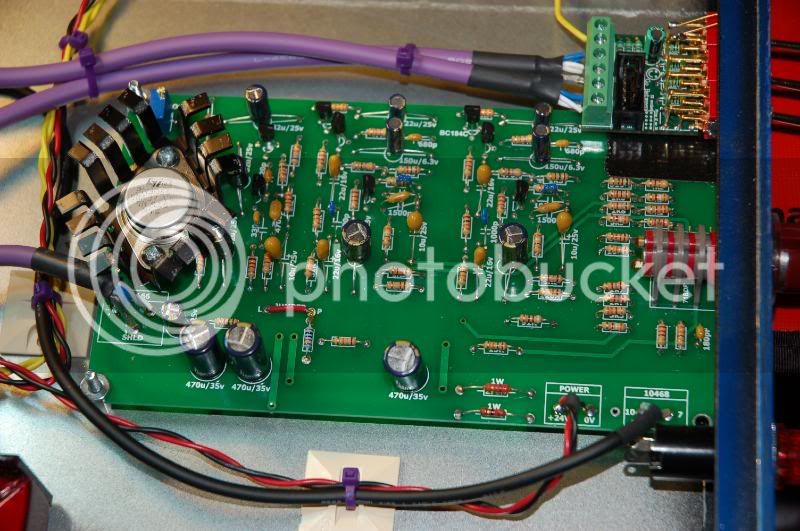
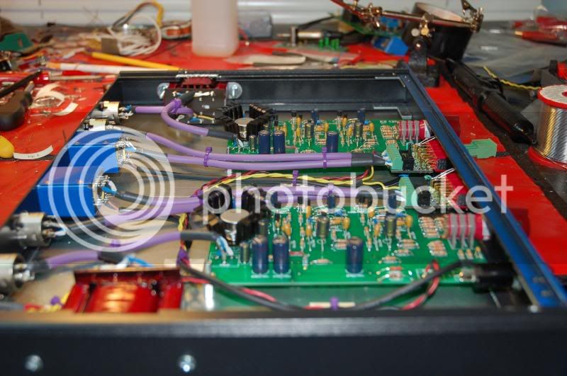
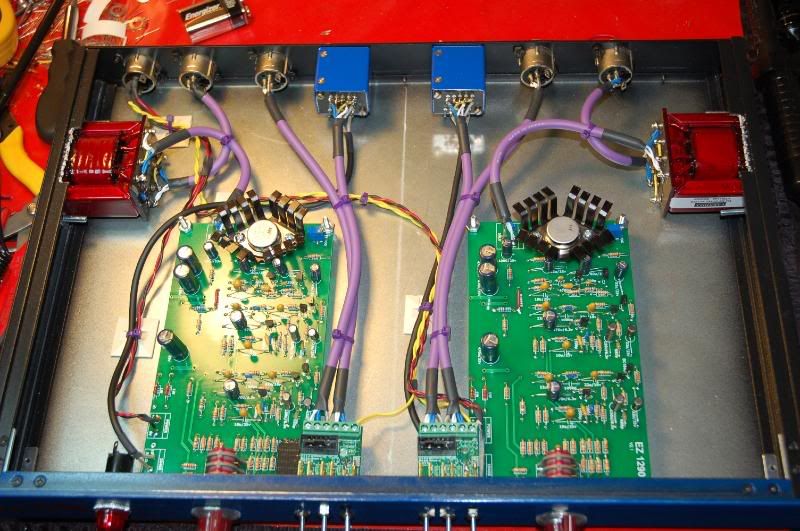
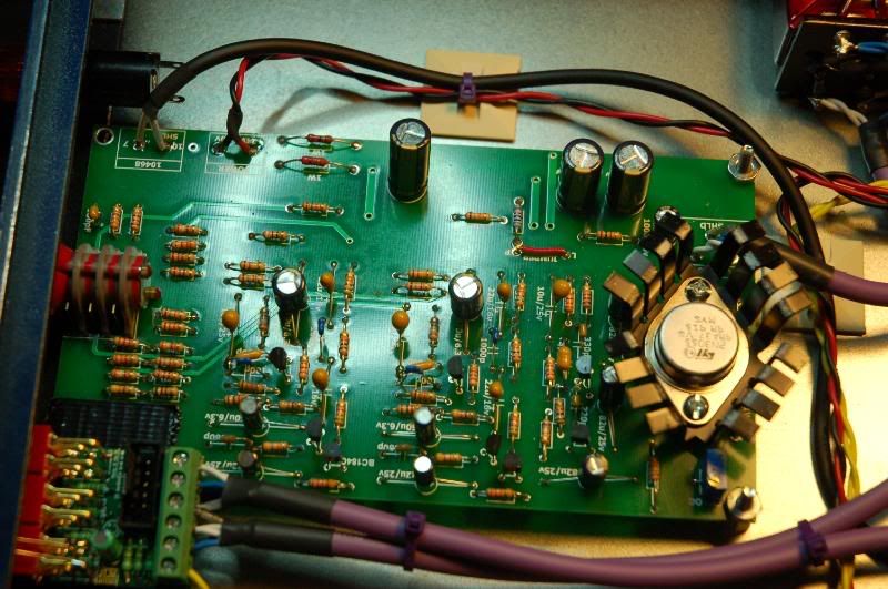
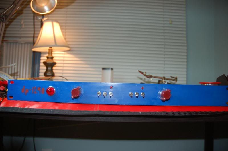
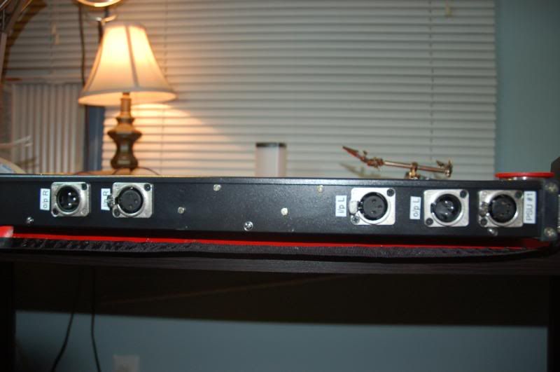
Neve 1290 build completed!!

GroupDIY Audio Forum

Help Support GroupDIY Audio Forum:

This site may earn a commission from merchant affiliate links, including eBay, Amazon, and others.
No sarcasm intended Sig, just maybe badly interpreted humour? Fader is usually used in conjunction with linear movement pots that is why I presumed (albeit falsely). Appologies for any misconstrued meanings (but isn't the smily there for that?).

Jim

Siegfried Meier said:
Bluzzi said:
The NEVE drawings call for a fader. A fader is just a pot with a linear (straight) interface instead of a rotary one. They are interchangeable.....and will fit a 1RU a lot easier. ;D

Jim

Wow thanks for the tip (lays down sarcasm pretty thick).  Of course I wasn't actually referring to a linear fader, I was referring to a rotary fader.  I was asking what others used for a ROTARY fader.

Thanks for the info 3nity - does the 5k cut the signal completely?  Or is that what the 10k does?  I can always replace with the P&G type later on, good to know regular alphas work too for the time being.

Thanks,
Sig
 
It was actually me that was intending sarcasm... :) there's your smily.

Anyway, whatever.  Thanks for your help.  So, is a 10k Alpha pot what others have been using?  And is lin or log the preferred?  I guess it really doesn't matter if it's just a rotary pot anyway, it's just to turn down the volume.  I just need to know which one - 5k or 10k - cuts the volume fully.

Thanks,
Sig
 
I went with a 10K log Bourns.  It doesn't seem to impart a sound on the signal and I thought this made more sense as it replaces a fixed 10K resistor.  No sound passes CCW, but it does seem to cut very quickly from full volume to rotating the knob 25%.  For me it's not a big deal as I'm not looking to use the pres as distortion boxes.

Todd
 
Words get in the way sometimes eh? (in good Canadian response).

Here is what I found in the NEVE manual. Don't forget that they refer to a full 1073 or 1084 with EQ section. If you have only a 10K around use that. Hope it helps.

---------
The high pass filter in both the 1073 & 1084 modules is a passive design and as such must be
correctly terminate d toachi e veamaxi mall yflatre
In order to achieve this there is a 5k1 resistor fitted inside the module on the back connector
between pi n E( 0v) an d pinK (fad er send)s eedia
In situations where the fader connection is not used (most Neve 45 series consoles except
BCM10's) the nt heresis torrem ai nsin
In situations where the fader connection is used (BCM10's and AMS Neve 1073/1084 racks)
then the 5k1 resistor should be disconnected and replaced with a fader or potentiometer whose
value is 4k7 or 5k

-----------

author=Siegfried Meier link=topic=20152.msg416290#msg416290 date=1244656946]
It was actually me that was intending sarcasm... :) there's your smily.

Anyway, whatever.  Thanks for your help.  So, is a 10k Alpha pot what others have been using?  And is lin or log the preferred?  I guess it really doesn't matter if it's just a rotary pot anyway, it's just to turn down the volume.  I just need to know which one - 5k or 10k - cuts the volume fully.

Thanks,
Sig
[/quote]
 
Ok cool thanks.  I've got some 10k pots here - labelled B, I think that's linear...I'll try that and see what happens.  Like I said, I can always swap out later for the real P&G ones.

Sig
 
I dont know what you trying to achieve Sig.
But an ouput trimmer is only good when the gain switch steps are just to bigs....less precission.
thanks
 
are these jumpers i need to wire? this photo is of a version 2.0 board. mine are v2.1 so they're a little different. any ideas?
 

Attachments

  • jumpers.jpg
    jumpers.jpg
    5.5 KB · Views: 1,293
I finally finished my 4-channel EZ1290, but I haven't had a chance to bias it yet (I will be borrowing a scope on the weekend to do it). This being my first DIY project, I'm happy to say that everything seems to work with only a few issues.

1) I used the JLM go between... the phase and the pad work, but the phantom doesn't... well the actual phantom might, I'm afraid to try a condenser mic on it. However, the LED's don't turn on, and if any of the phantom switches are turned off, there's a wicked hum. So if all the phantom switches are on, there's no hum, but if you turn any of them off, the hum starts, and with each channel that you turn off, the hum gets louder.

2) I'll have to confirm this, but the loudest point on the gain switch is just counter-clockwise of 12 o'clock. However, I based my engraving on Martin's files which has the loudest point (75db) just counter-clockwise of 6 o'clock. My PCB is component side up, but it's almost as though if I put it component side down, it would be correct. Strange. Did I miss something here?

3) The loudest point on the gain switch is just noise. It was really freakin' loud so it may just be distorting the AD inputs but it seemed unnaturally distorted. I don't know if this is just because it hasn't been biased yet though. I also used a 31267 as my input transformer and basically took a stab at how it should be wired... I think that it's right but I'm not positive. So this may also be a contributor.

Any help would be appreciated! Thanks everyone!

Ryan

 
Hello all

Loving my 2ch ez. I want to use it on the 2 bus to add some weight. What's the best way to add line ins. Regular U pad before th in xfo? Direct in after the in xfo. Switch in a carnhill line xfo($$$)?  Any help?
 
Any takers?

rmccam said:
I finally finished my 4-channel EZ1290, but I haven't had a chance to bias it yet (I will be borrowing a scope on the weekend to do it). This being my first DIY project, I'm happy to say that everything seems to work with only a few issues.

1) I used the JLM go between... the phase and the pad work, but the phantom doesn't... well the actual phantom might, I'm afraid to try a condenser mic on it. However, the LED's don't turn on, and if any of the phantom switches are turned off, there's a wicked hum. So if all the phantom switches are on, there's no hum, but if you turn any of them off, the hum starts, and with each channel that you turn off, the hum gets louder.

2) I'll have to confirm this, but the loudest point on the gain switch is just counter-clockwise of 12 o'clock. However, I based my engraving on Martin's files which has the loudest point (75db) just counter-clockwise of 6 o'clock. My PCB is component side up, but it's almost as though if I put it component side down, it would be correct. Strange. Did I miss something here?

3) The loudest point on the gain switch is just noise. It was really freakin' loud so it may just be distorting the AD inputs but it seemed unnaturally distorted. I don't know if this is just because it hasn't been biased yet though. I also used a 31267 as my input transformer and basically took a stab at how it should be wired... I think that it's right but I'm not positive. So this may also be a contributor.

Any help would be appreciated! Thanks everyone!

Ryan
 
rmccam said:
1) I used the JLM go between... the phase and the pad work, but the phantom doesn't... well the actual phantom might, I'm afraid to try a condenser mic on it. However, the LED's don't turn on, and if any of the phantom switches are turned off, there's a wicked hum. So if all the phantom switches are on, there's no hum, but if you turn any of them off, the hum starts, and with each channel that you turn off, the hum gets louder.

Sounds like a wiring issue, do you have an inside shot?

2) I'll have to confirm this, but the loudest point on the gain switch is just counter-clockwise of 12 o'clock. However, I based my engraving on Martin's files which has the loudest point (75db) just counter-clockwise of 6 o'clock. My PCB is component side up, but it's almost as though if I put it component side down, it would be correct. Strange. Did I miss something here?

The scale you used is probably meant for a vertically mounted 1290 board...not horizontally.

3) The loudest point on the gain switch is just noise. It was really freakin' loud so it may just be distorting the AD inputs but it seemed unnaturally distorted. I don't know if this is just because it hasn't been biased yet though. I also used a 31267 as my input transformer and basically took a stab at how it should be wired... I think that it's right but I'm not positive. So this may also be a contributor.

I used a 31267, and it's pretty darn quiet. The proper info on 31267 backwards is at Aurora Audio. Make sure to get all the sheilding...ie: switch and 31267 case. Basic crappy...but quiet wiring scheme is here: http://img200.imageshack.us/i/dsc02018.jpg/


you better post good quality pictures for us to see...
Phantom LED dont turn on? are they backwards? did you measure 48V going into the Go between?
Martin scale its for horizontal mounting not vertical! if you wanted vertical then turn the scale 90 degrees maybe?
Wheres your psu located?
 
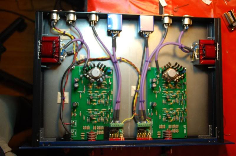
FINALLY FINISHED! posting some pics because I've realized just how helpful other people's pictures are to me when I'm building something. I like to think of it like listening to a reference mix when mixing your own material!

An enormous thanks to Martin for the boards and all the wonderful build info and help. You're the best!

It was a relatively easy build and Martin's boards are absolutely incredible both in design and in quality. A breeze to solder. It was pretty great to plug these in for  the first time and have them work for the first time! They haven't even been properly calibrated yet (don't have an oscilloscope, just "Mac The Scope" on my computer) and they sound great! Recorded a bunch of acoustic guitar. I really recommend this build to any newbie even with very basic understanding, it's still an easy build (I'm a newbie with very basic understanding).

If you do decide to build one, whatever you do, DON'T BUY THIS CASE:

http://webtronics.stores.yahoo.net/1u19ramochal.html

It was the biggest pain in the ass to cut and the only time I "cut a corner" on the cost. Not worth it. Spend the extra 15-20 bucks and get something that works. This one is not designed for audio gear! (See the pics and notice how I had to saw off the sides to fit the o/p transformers). And the XLRs barely fit the back because the cheap case has overlapping metal on the top and bottom.

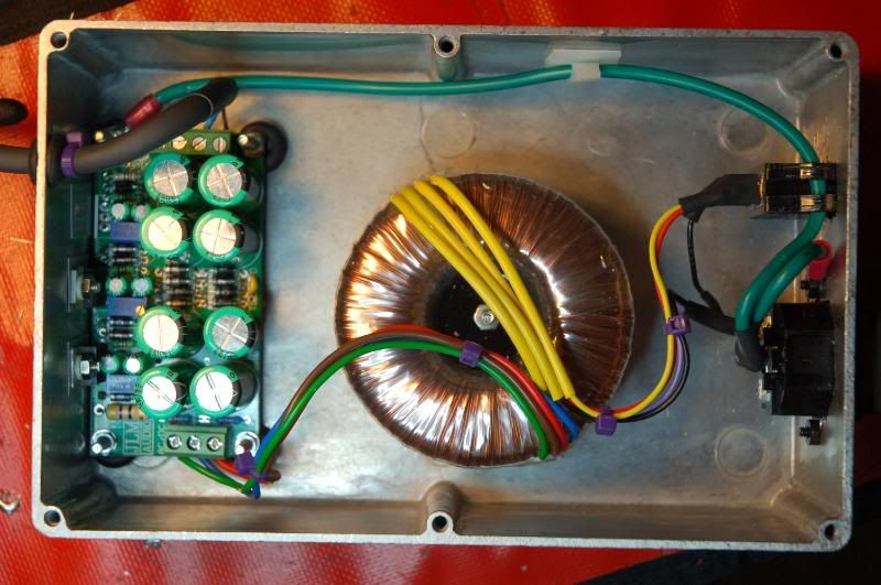
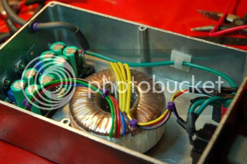
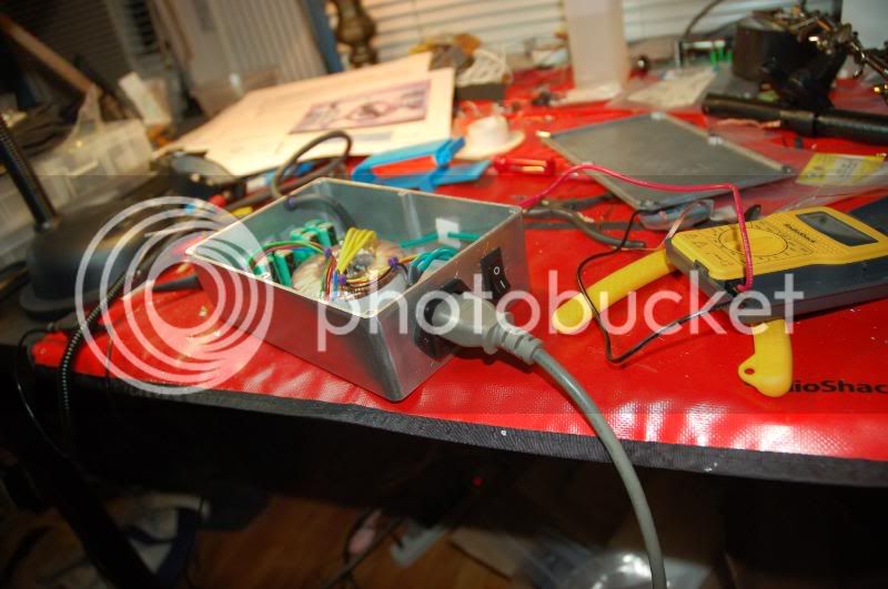
For the PSU I virtually copied Martin's assembly guide and it worked beautifully. Great design Martin ;)


Check out the shots and notice my miscalculation in the spacing of the Go Between boards and the 1290's! Here is living proof of why it's a good idea to double check EVERYTHING TWICE (=quadruple check once)

Also, you'll notice I haven't hooked up the pilot lamp. I read somewhere that these bulbs actually suck a lot of power and I don't want to compromise the pre's. Has anyone used these? Would it be ok to hook it up?

DSC_0002-1.jpg

DSC_0003-1.jpg

DSC_0005-1.jpg

DSC_0006-1.jpg

DSC_0007-1.jpg

DSC_0008-1.jpg

DSC_0009-1.jpg

DSC_0010.jpg

DSC_0011.jpg

DSC_0012.jpg

 
Wow, great job Dan!! Thanks for the kind words and nice pics. I know you did quite a bit of homework on this before you started and it looks like that paid you big dividends!! Happy Tracking!! You can get fairly close to being calibrated if you adjust the trimmer so that TR3 collector (the TO-3 casing) reads 22.6 volts. That's with the PSU adjusted to 24.05V.

You bring up a good point re: front panel layout. If I'm building something new/unfamiliar I usually do a cardboard prototype panel first to see how everything fits in real life. That's saved me from wasting metal and energy a bunch of times.

Ryan,

Are you still having problems? Re: your questions:
1) I used the JLM go between... the phase and the pad work, but the phantom doesn't... well the actual phantom might, I'm afraid to try a condenser mic on it. However, the LED's don't turn on, and if any of the phantom switches are turned off, there's a wicked hum. So if all the phantom switches are on, there's no hum, but if you turn any of them off, the hum starts, and with each channel that you turn off, the hum gets louder.

I'm not sure on this. I would try to wire w/o the Go Between first to simplify things and see if that works.

2) I'll have to confirm this, but the loudest point on the gain switch is just counter-clockwise of 12 o'clock. However, I based my engraving on Martin's files which has the loudest point (75db) just counter-clockwise of 6 o'clock. My PCB is component side up, but it's almost as though if I put it component side down, it would be correct. Strange. Did I miss something here?

Not sure I understand. You can adjust the knob/pointer to point in any direction you want in relation to the switch shaft.

3) The loudest point on the gain switch is just noise. It was really freakin' loud so it may just be distorting the AD inputs but it seemed unnaturally distorted. I don't know if this is just because it hasn't been biased yet though. I also used a 31267 as my input transformer and basically took a stab at how it should be wired... I think that it's right but I'm not positive. So this may also be a contributor.

Ah, oscillations. Using shielded wire and properly spacing input signal away from output signal should take care of it. Also, space the transformers a bit. If not, you may try swapping out TR3, or try a regular 10468.

HTH,

M.
 
By the miracle of reassembly, everything now works!! I reseated the +48V and all problems fixed themselves (you gotta love when that happens). The only issue still is the front plate which is wrong... the loudest point of the preamp is at 12 o'clock, but 70 db is at 5 o'clock. It's really not a big deal though... you don't really need the dB values anyway. I'll redo the front plate at some point but for now I am just proud to say that I finished my very first DIY build! It sounds effing sweet too (which is all courtesy of Martin)! I will post pictures soon.

Thank you everyone for your help, especially Martin, who managed to field my incessant annoyances with ease. I really do appreciate it.

Ryan

 
desol said:
Martin...how trusty are those trimmers at staying put? Drift?

Hi Desol, they're very stable AFAIK. Are you having problems?

rmccam said:
By the miracle of reassembly, everything now works!!

Good work!! Re: the gain switch, to me it still sounds like you need to loosen the knob and rotate it in relation to the shaft in order for it to read correctly on the front panel. If that's not the case and you're getting max gain six clicks from the "bottom", you probably have some incorrect values on the resistors surrounding the switch, or you have the stop pin in the wrong place (move it 180 degrees from where it is now).

EEMO1 said:
how do you ground a pre with an external psu?

xlr pin 1 to.... looking at the pics... ???

Sorry, I'm not sure I understand the question. Are you talking about the 4 pin power XLR, or the mic in/line out XLR? For my external PSU's I run the 4 pin XLR like the assembly guide, but I also run earth to pin 2 and connect that to the preamp case. So from the wall outlet I run the earth connection to the PSU case, pin 2 of the XLR connect, and the earth connection on the ACDC (the top right mounting hole).

Let me know if that answers your question.

Best,

m.
 
Back
Top