A Tube Mic

GroupDIY Audio Forum

Help Support GroupDIY Audio Forum:

This site may earn a commission from merchant affiliate links, including eBay, Amazon, and others.

analag

Well-known member
Joined
Apr 23, 2005
Messages
1,944
Location
Mars
I have had a couple of requests for one of my tube mic schemos from time to time, so here we are.
http://www.twin-x.com/groupdiy/albums/userpics/R8.JPG
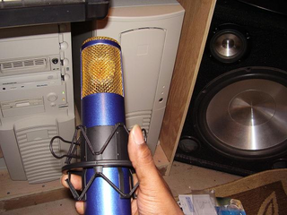
I used my Nady TCM1050 PSU to power this one, though I modded it to supply 80V and 160V to the capsule. B+ is 200V, but 180V will work just as well.
 
A Peluso CEK-367 was used with this schemo. And if you should use 180V B+ then the 1.5 Meg resistor must be scaled down to 1.2 Meg to provide 80V at the capsule.

2ed4f474.png
 
Are the capacitors on either side of the capsule just there to represent the capsule diagphrams? No capacitor between the capsule and the tube grid?
 
Yup the back to back caps represent the capsule and no cap between the capsule and the tube grid (Neumann style). I only can tolerate one coupling cap in a microphone.
 
[quote author="analag"]Yup the back to back caps represent the capsule and no cap between the capsule and the tube grid (Neumann style). I only can tolerate one coupling cap in a microphone.[/quote]

Interesting, thanks for sharing the schematic! What's your opinion on the importance of the other caps on the high impedance side of the circuit (and other side of the capsule)? Do you feel that they are less critical?

Martin
 
All caps have a sonic impact on the circuit in which they reside, some less so than others. For example if you can build a mic without a cap between the capsule and the grid, then by all means do so. The cap between the plate and the transformer should be given careful consideration. Gus and I have discussed this (among other things) extensively off the forum. There is a lot to be studied and I have learned a lot from the man.
 
Yeah, I firmly believe in the "everything is important" way of looking at things in a circuit. Perhaps "until otherwise proven".

Looks difficult to design an externally polarized microphone with only ONE coupling cap like you suggested. Even if we don't use a cap between capsule and grid, the other side of the capsule needs to be connected somewhere. Interesting topic.

So how did your circuit sound and work? (especially with that interesting 1k resistor in there...)

Martin
 
It's a combination of three mic schematics. I took the 6AU6 from the Sony C800G, the front end from the Neumann U48, the cathode circuit from the AKG C12, mix them all up together and tweaked it to taste.
The circuit sounds great, but the capsule and the acoustic chamber that houses it, is just as important if not more so.
 
Speaking of that interesting 1k resistor, between the low side of the transformer primary (really the secondary, using it in reverse) and ground. Is that helping the tube plate loading, since in the C800 the output transformer was 9:1 turns ratio and you are using a 5:1 ratio?
 
The published Rp for a triode connected 6AU6 is 7.5K but at the B+ and plate current that a tube mic head amp is run, throws all that out the window. I tried a 5:1 ratio and it worked. So between 5:1 and 9:1 is workable shall we say?
 
[quote author="analag"]Heater is DC regulated.[/quote]
I suspected as much. There is an interseting example in RDH using a 6AU6 in a mic pre. The anode and screen are connected together to ground (to reduce hum because a heater pin is right next to the anode pin) and the screen is used as the anode. Characteristics are apparently similar to the triode you get by tying anode and screen together but you need to watch screen disippation (0.65W) but not a real problem in a pre.

What made you pick a 6AU6? It seems a much underated valve to me.

Ian
 
look at the circuit

The AKG C12 is one hint

I think it looks more Schoeps 6au6 than sony.
 
I just built Royer's Country Boy circuit into an MXL V57M. The Country Boy circuit was inspired by the Altec M11 circuit, which used a 6AU6 as a cathode follower, although with the 5840 cathode follower the grid leak bias results in a lower voltage on the capsule, lower sensitivity, a darker sound. I was going to try the plate out 5840 circuit next, but maybe I'll try this 6AU6 circuit instead. Damn, I need to save up some money for good capsules.
 
[quote author="SSLtech"]I don't know about the CEK-367 -Does it not have an inbuilt HF boost?

Keith[/quote]

Look at the 500pF that's tied between the plate and cathode circuit. Rounds it off nicely.
 
Greetings to all! Is glad to be present again.
I too experiment analogue 6AU6-6Ж4П (6J4P) Russian manufacture, but with the caps. My caps have capacity (depending on diameter) from 90pF up to 135pF. And from capacity of a cap it is necessary to select the loading resistor of a grid tube-at me quite good results in a sound with resistors from 100Mom up to 820Mom (the more face value of the resistor, the turns out sounding more fatly, but it is not always better) turn out. On an output of a lamp tried to put the target transformer through the film condenser 2.2uF/250v from "Octave" MKE-9-quite good results, and also I experiment with transformerless an output on field transistors.
 
hello everybody.
I have been putting together this beautiful microphone lately and it's now time to test it (and of course, to ask questions):
with the capsule connected shall I read +80V between the back and front plate?

any suggestion will be much appreciated!

mattia.
 

Latest posts

Back
Top