Line mixer/summing box...with That 1240's

GroupDIY Audio Forum

Help Support GroupDIY Audio Forum:

This site may earn a commission from merchant affiliate links, including eBay, Amazon, and others.

radiance

Well-known member
Joined
Jun 4, 2004
Messages
3,228
Location
the Netherlands
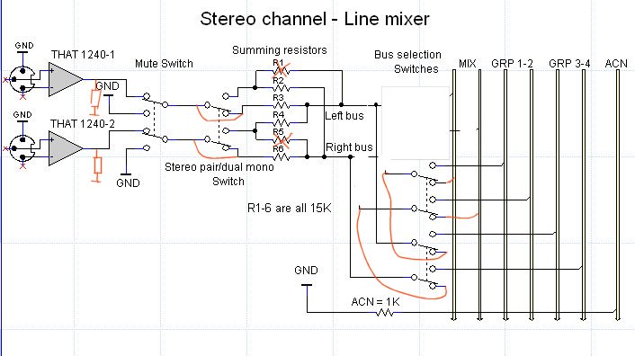
This is something I want to build, nothing special and pretty straightforward. It's basicly a 10 stereo channel summing box with 6 busses. That's 1 stereo mix bus and 2 stereo groups. All inputs have That 1240 line receiver's which are simmilar to the INA134.
LineMixSteCha1.jpg


Summing will be done with something like this (and that's where I have the resistor values from as well :oops: )

Any thought's?
I'm struggeling a bit with resistor values since there are a couple of scenario's in terms of channel count. For example, when all stereo pairs are set to "dual mono" there are 20 channels to be summed. When all's set to stereo it's 10 channels.....and then there's the 2 stereo groups which can be assigned to the mix bus as well. So worst case is 24 channels that need to be summed...
 
I'm not sure if that kind of passive mono summing will result in the same level as when switched to stereo...

have you thoght about the that1200 line receiver?
http://www.thatcorp.com/datashts/1200data.pdf
 
Well, I'm not really sure but AFAIK it should not be a problem cause it's a zero-ohm summing bus right?

Yes, that 1200 line receiver. What are the benefits compared to the 1240?
It's almost twice as expensive as the 1240....
 
Ater thinking about this mono summing for a while I have my doubts...
When I have 20 channels and the all have 30K (R1 + R2) between them, I end up with 6K between the left and right bus. Hm, I should do some more reading on the subject I guess...
 
I think this would be a more elegant aproach...but still, everytime a stereo channel is set to "dual mono" ,resistance between the left and right bus decreases. Would this be a serious problem?

LineMixSteCha2.jpg
 
[quote author="Samuel Groner"]Don't we need a pair of summing resistors (and ground-sensing resistor) for each bus?

Samuel[/quote]

You mean after R1-4? Well, actually R1-4 are my summing resistors.
I guess that this aproach for dual mono summing is not going to work right?
Also, the summing opamps are set up as a zero ohm summing bus (see link in first post...)

Maybe I should remove R2 & R3 and the "Stereo pair/ Dual mono" switch altogether and just stick with stereo summing....In that case R1 and R4 are the summing resistors

What do you mean by Ground sensing resistor? Maybe that's what I've called the ACN Ground resistor. What I did not know was that I needed one for EVERY bus. I thought 1 ACN Ground path for all busses was enough...
 
[quote author="Samuel Groner"]You need individual summing resistors for each bus I think (so 6x4 resistors total). The mono summing should work as shown.

Samuel[/quote]

What about adding the summing resistors right behind the stereo/mono switch? Than I just need two resistors.
I mean the zero ohm summing bus does not care if channels are added or substracted right?
 
You could skip R1 and R5 in this place. If you wire your routing in series to make sure only 1 bus is connected at the same time (bbm switch) you could save the feeding resistors for each bus and also save a switch, but this will keep always a bus connected.
Your summing bus will probably not care if a channel is added, but the receiving summing amps will if their inverting inputs (the summing node) are connected to each other. Don't miss Samuels quote about the required reference to gnd for each channel, else the feeding buffer is still floating.
LineMixSteCha1_edit.jpg


edit drawing
 
[quote author="Harpo"]
Your summing bus will probably not care if a channel is added, but the receiving summing amps will if their inverting inputs (the summing node) are connected to each other.[/quote]

Bus selection will be done with a Lorlin rotary switch so the channel will only be connected to one bus at the time.


[quote author="Harpo"] Don't miss Samuels quote about the required reference to gnd for each channel, else the feeding buffer is still floating.
[/quote]

I don't get this. Is this the resistor you draw connected to the output of the 1240?

The THAT 1240 line receiver has a reference to ground (not drawn in my schematic) Is this what you mean by "reference to ground for each channel?
LineReceiver1.jpg


Thanks all....
 
Thanks...

One more question though...What's the difference between the 1240 and the 1200? Considering the 1200 is almost twice as expensive, would it be worth to use it on a line signal summing mixer. I'm only going to sum outputs of my Lynx Aurora so no mic's or strange input sources...
 
Ok..thanks..I'm learning here :grin:

[quote author="mediatechnology"]
If the load on the 124X/120X output is less than 2K I would consider a buffer. You could also use the 128X dual (SMT-only) which has 600 ohm drive capability.[/quote]

What exactly is a "load"? Is this the summing resistor or is it the "reference to ground" mentioned earlier by Samuel.
Also, looking at the pic below, does the 1240 has a reference to ground by means of pin 1? Or do I have to ad one...??

LineReceiver1.jpg


Sorry for all these questions but I started reading all I could find about summing and mixers and it gets confusing with all these contradicting opinions and ways of doing things.
The lesson I learned is that if I ever want to build something like this I just have to start and see how it goes. OTOH.. I want it to be absolutely right ..., since this is going to cost quite a lot...with all these pamps, switches, relay's and also pcb's. I know, there is no "right way" of doing this but I want to avoid mistakes...
I'm having a great time learning Rimu pcb software btw!!. I can highly recoment this for beeing very easy to get started with :thumb:
 
Anybody feel free to correct me if I'm wrong here, I'm still learning as well.

A load is what you have connected to the output of a circuit, in this case, your 1240s. Glancing at what you have here, I think the load presented to the 1240 would be the parallel of your ground sensing resistor and the summing resistor.

Getting parallel resistances requires this formula:

R_Total = 1/( (1/R1) + (1/R2) + ... )

The output of a circuit should generally be loaded with 10x its output impedance. For example, if the output impedance of the circuit is 1k, then ideally it should be loaded with a 10k impedance or higher. This rule is not hard and fast, of course.

An ideal opamp has infinite input impedance and a zero output impedance, which allows for a large variety of loads to be connected. In reality, however, real world opamps will have some output impedance and a finite ability to deliver adequate distortion free signal to very low impedance loads. The datasheets should provide you with the info you need to choose the correct impedances for the circuit.

Wayne has worked with these many times and I would follow his recommendations as far as loads go. Another caveat is to have suitable bypassing of your power supply at the V+ and V- pins, as the 1240 is a rather wideband amplifier. I see 100n caps in the 1240 sheet.

-Matt
 

Latest posts

Back
Top