4rail PSU layout... Etch file available for download!

GroupDIY Audio Forum

Help Support GroupDIY Audio Forum:

This site may earn a commission from merchant affiliate links, including eBay, Amazon, and others.

mitsos

Well-known member
Joined
May 4, 2007
Messages
2,886
hey all, I've working on a 312 pre (for ages, it seems), finally sent the files to get a prototype board, but it needs a 4th power rail, so I thought I'd trow together a small PSU.  I've drawn a bit from each of Keith's, Mnats', and JLM's. Anyway, I'd appreciate any comments, not sure if I'm gonna get this made, might make it a 5rail if I ever do a board run.

Anyway, I like the way JLM's 5 rail has each bipolar running directly off the rectifiers, instead of regulating then regulating again, that's what I got from there.  I took the phantom circuit from Keith's and the layout is basically Mnats', with an additional rail and phantom.  I also made a diode footprint that can take both axials (1N400x, etc) and TO-220 diodes (MUR860, etc), but no bridge footprint.

It's textbook LM317/337.  All traces are 40mil, with 20mil clearances.  Just wondering if people could take a peek at the images. Once done, if people would find this useful, I can post an etch file.

As is, it is about 3.5 x 2.2 inches.

Thanks in advance

EDIT See below for updated/corrected files
 
About the pcb layout...right now it's quite hard to attach heat sinks to the regulators.

Either line them up, so you can use 1 big strip of metal (with isolation pads) for all regulators,

put them on the side of the pcb, so you can attach them to the chassis (with isolation pads),

or give each regulator more space around it so you can use individual heat sinks.
 
as radiance already said,
C6, C7, C11 and C16 should be placed close to the regulators,
keep the cathode side carrying potential at the MUR's metal tabs isolated or rearrange the diodes,
schematic and pcb layout seem either inconsistent or from different generations (missing link between D7/D8 and C1, leaving IC2 without feeding input only on schematic),
you might consider to put a higher wattage resistor in front of IC4, so the regulator could run cooler or a smaller heatsink could be used,
an additional load resistor (maybe with LED in series to please your eye) from each rail to 0V could ensure that the min.load current requirement of the regulators gets drawn. (these 240R's and 220R only draw 5mA, but most linear regs want a 10mA up to 15mA min.load current for predictible results.)
just my 2ct.
 
ok, thank you guys for all that.. I also noticed I left out a connection between the phantom "bridge" and ground... oops. Anyway, I reworked the diode package to have 2 anode pins (on schematic) this way the dual pads on the board are "independent" and I have to physically connect them which led to less DRC errors.

Srenda, thanks for the link, I do remember that thread. Although I think it's only applicable in cases where there is a big draw on the 48V rail, I wouldn't hurt to have bigger caps. I enlarged the cap footprints as much as possible, but to do any more may mean a larger board, so if you guys think it's good, I'll do it, otherwise, I think this is good for my purposes. I also put a jumper in place to choose between voltage doubler/tripler, so this could be used with lower voltage trafos.

Rearranged the diodes to not have any cathodes close to each other. I had thought to put heatshrink on them at first, but I this is much better.

Changed the resistors to 120R which should lead to a bit over 10mA draw unloaded. Please correct me if I'm wrong. Phantom changed to 121R and 4K53.

Put the film caps closer to the regulators.

And of course, heatsinks should now fit. Most small heatsinks are 13mm wide, and there is more than that around each regulator. I did not even try to line them up the way JLM has because I don't think I could keep it single sided.

I wonder if I should change the film cap at each output to a larger value lytic? Datasheet says 1-1000uF tant or lytic improves transient response (what is transient response in a regulator?). Maybe 10-22uF might be better or is a small (0.1uF) film ok?

EDIT Added mounting holes.


mitsos said:
Anyway, I reworked the diode package to have 2 anode pins (on schematic)
seeing the metal sheet as the 3rd.pin, you have 2 cathode pins. Will not matter for this board layout, but I'd probably correct the library to not accidently connect the wrong pin/heatsink to a groundplane for a future design. YMMV.

Changed the resistors to 120R which should lead to a bit over 10mA draw unloaded. Please correct me if I'm wrong. Phantom changed to 121R and 4K53.
Try to place the 120R's close to regulators output pin.
What type of regulator will you use for IC1? If your plan shows a TL783, this type wants 15mA min.load current to maintain regulation.
The pin spacing of the 4k53 (dissipating 0.5W) might be a little narrow for a 1W part and actual distance to C12 might fry this cap. Two R's in half value series or double value parallel config might be easier to source.

I wonder if I should change the film cap at each output to a larger value lytic? Datasheet says 1-1000uF tant or lytic improves transient response (what is transient response in a regulator?). Maybe 10-22uF might be better or is a small (0.1uF) film ok?
The LM317 datasheet of the National part recommends an at least 1uF tantalum or 25uF aluminum electrolytic for stability. You might have these already on your connected load, but its good practice to have them on board.
Line transients occur from input side (the wall outlet voltage isn't a constant and varies by time of day for heavy load switching or disconnecting inductive loads) or output side (FI kickback from relais coils). Load transients occur when the current demand of your connected load changes (some idiot made a sound in front of your mic and now your amp has to work a little more than idle to get the level up to the dialed in gain). The transient response of your regulator is the time needed for regulating these with more or less artifacts (see datasheet response curves) and the cap helps to keep them in ranges.
 
Harpo said:
mitsos said:
Anyway, I reworked the diode package to have 2 anode pins (on schematic)
seeing the metal sheet as the 3rd.pin, you have 2 cathode pins. Will not matter for this board layout, but I'd probably correct the library to not accidently connect the wrong pin/heatsink to a groundplane for a future design. YMMV.
I kinda see what you mean, but not completely. I made this part for this specific reason, I have some TO-220 diodes that I'd like to use for this and so thought it'd be good to use.

Changed the resistors to 120R which should lead to a bit over 10mA draw unloaded. Please correct me if I'm wrong. Phantom changed to 121R and 4K53.
Try to place the 120R's close to regulators output pin.
What type of regulator will you use for IC1? If your plan shows a TL783, this type wants 15mA min.load current to maintain regulation.
The pin spacing of the 4k53 (dissipating 0.5W) might be a little narrow for a 1W part and actual distance to C12 might fry this cap. Two R's in half value series or double value parallel config might be easier to source.
done and done. Thanks for pointing that out. I went with 2x series resistors. 2k26

I wonder if I should change the film cap at each output to a larger value lytic? Datasheet says 1-1000uF tant or lytic improves transient response (what is transient response in a regulator?). Maybe 10-22uF might be better or is a small (0.1uF) film ok?
The LM317 datasheet of the National part recommends an at least 1uF tantalum or 25uF aluminum electrolytic for stability. You might have these already on your connected load, but its good practice to have them on board.[/quote]
I chose a 22uF 63V panasonic FC footprint but left room around it so that other, potentially larger caps could fit.


Put a name/version/date on it and give it a try. :)

As already said in a previous post, I'd probably move parts around IC4 further to the right to get an optional series resistor (maybe upright) in front of this regulator. YMMV. Aux DC voltage might be set to 12V for relais,LEDs,... and feeding this regulator with 25V raw DC - depending on connected load - else might call for a bigger heatsink. It could easily be shorted out if not required, but might make it a little more universal.
If IC1 is a standard LM317 (not LM317-HV or a TL783), at least a placeholder for a 1W zener (something like 1N4747 ... 1N4751) in parallel to D1 might not be the worst idea.
 
yeah, I'm about ready to play with this one. Gonna try to etch it over the weekend. About the series resistor, how do I figure out it's value?  Would I just add up the current consumption on the rail (count LEDs, relays, etc?)?  Add to that the internal current draw of the regulator? Is that 12V/120R=10mA? 

but why the 1W zener?
 
mitsos said:
yeah, I'm about ready to play with this one. Gonna try to etch it over the weekend. About the series resistor, how do I figure out it's value?  Would I just add up the current consumption on the rail (count LEDs, relays, etc?)?  Add to that the internal current draw of the regulator? Is that 12V/120R=10mA? 

but why the 1W zener?
With 18VAC transformer the raw DC voltage after diode drop in the rectifier in front of your regulator will be about 24VDC.
Your regulator might be set for 12V output. To maintain regulation it needs a 3V higher voltage on input.
Connected load to this 12VDC might be 250mA for LEDs, relais, current setting network at your regulator, .. just add it up.
(18VAC * 1.414 - 1.4V) - (12V + 3V) = 9V to drop
9V / 250mA = 36 ohms
9V * 0.25A =  2.25W
A 36R 3W to 5W resistor should work for previous example.

internal current draw of the regulator? IMHO negliable about 50-100uA. You probably questioned the current draw of the voltage setting network. Vref / RIset = typ. 1.25V/120R = about 10.4mA. (Vref can be 1.2V up to 1.3V and resistors come with tolerances).

If you set this Aux.voltage to 20V instead of 12V, you could use 24V relais. Relais pickup and dropout voltage most often specified.at 75% should allow save switching even at reduced supply voltage and will run it way cooler.

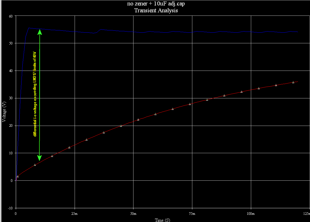
The zener, with a voltage doubler in front only needed for the LM317 - the LM317-HV has diff.i-o 60V (not enough with voltage tripler in front), the TL783 has diff.i-o 125V - the zener clamp should help to keep the differential i-o voltage for the LM317 within its max.40V limits for normal power-on operation. With C12 at the adj.pin this might take some time to charge and while charging the diff.i-o might exceed the max.i-o difference. It has flaws because a shorted output will last longer and draw more current than the zener can take. Two resistors and an easier to source transistor with appropriate rating could catch this flaw, but then you'd better picked the TL783 in the 1st.place.

A crowbar would be another nice to have insurance, but needed parts (fuse to blow, scr, comparator, zeners, resistors) probably would exceed availiable space.
 
Ok , cool, just as I thought on the series resistor. The current draw of the regulator I was talking about the voltage setting part of the circuit. OK, simple then.. but does it go after the filter cap or before?

about the zener.. when you say the voltage difference is not enough with a tripler, you are comparing input to 0V because of the adj-bypass-cap time-to-charge? Until this charges the I-O difference is full input-0V? I think I got it now... I am thinking a 50V zener woudl be best for a normal 317, since with 18VAC and a tripler, Vi = 76V or so, a 50V zener would drop this to 26V right, and yet when the cap is charged, it would see Vi-Vo=76-48=28V and so would not conduct, right?

thanks again for all the great ideas. Gonna stick this in there as well and post an updated and "final" schemo (changed the voltage set resistors back to 220R except for Aux, although they would all depend on what voltages are required, I suppose).

cheers!
 
ok, so here is the schematic, layout and etch file. I couldn't figure out how to make a small pdf, or how to export a vector file from eagle... SO, I made a pdf with photshop, but to keep the quality, it ended up 3MB, so I put it on rapidshare. See link below. If anyone can offer tips on how to save small, good quality etch files with eagle, I'd appreciate it.

Anyway, when printing the etch file, just remember it is 3.35 x 2.25 inches. All info needed should be in this thread, if anyone rushes off and etches this before me, please post back the results. Test it out of circuit first of course!


link to etch file:
http://rapidshare.com/files/313116245/4rail_etch.pdf
 
Mitsos, could you check if parts spacing is sufficient to get heatsinks for IC2,IC3,IC4 in between (between IC4, D15, C16 it looks a little tight).
I liked the screwclamp terminals better than the 0.1" spacing molex, but YMMV.

mitsos said:
about the zener.. when you say the voltage difference is not enough with a tripler, you are comparing input to 0V because of the adj-bypass-cap time-to-charge? Until this charges the I-O difference is full input-0V? I think I got it now... I am thinking a 50V zener woudl be best for a normal 317, since with 18VAC and a tripler, Vi = 76V or so, a 50V zener would drop this to 26V right, and yet when the cap is charged, it would see Vi-Vo=76-48=28V and so would not conduct, right?
Yes for a LM317-HV, coming with a max.differential voltage of 60V. The LM317 has a max.differential voltage of only 40V that you don't want to exceed, so using a 50V zener here wouldn't save the regulator. Try a 30V or 33V part (maybe 1N4751 or 1N4752) instead.
The LM317-HV seems safe enough for a voltage doubler in front so you could leave the zener out, but a tripler might take it over the edge, so your 50V zener should fit. Keep the zener conducting timeframe as short as possible. Being only a 1W part, a current limiting resistor might be the safer bet.

Maybe this simulation pics can visualize it better. The blue trace showing the unregulated raw DC at the regulators input, might be even higher, at least with a voltage tripler in front. The red trace showing the rising DC output voltage as the 10uF cap between adj.pin and 0V charges.
LM317_10uFcap_No_zener.gif


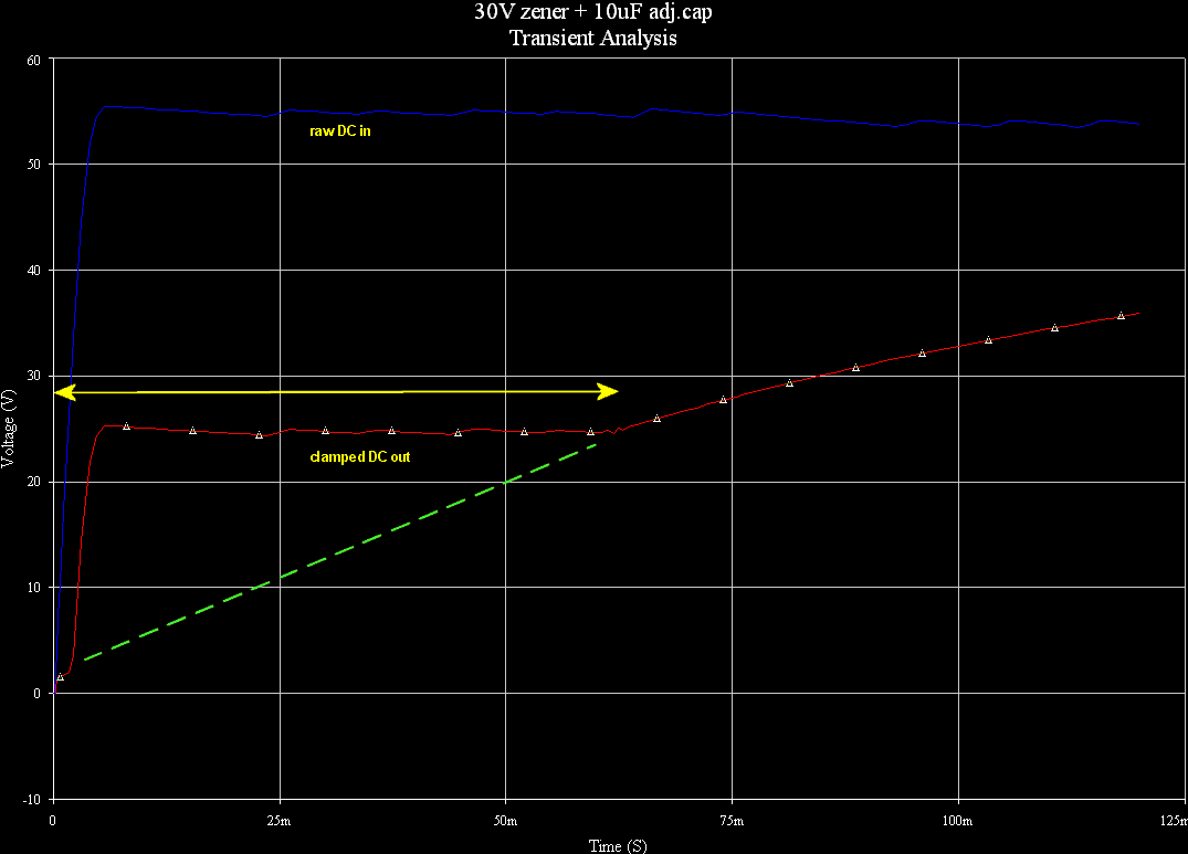
The same, but now with the 30V zener across the regulator. The red trace is the clamped DC output voltage. The yellow arrowline showing the zener conducting timeframe. The dotted edited green line without the zener, maybe exceeding the max.diff.i-o voltage.
LM317_10uFcap_30Vzener.gif
 
Thanks for the graphs Harpo!

I will double check the IC spacing, I thought I had spaced them to fit the half-inch wide (13mm) ones, with a bit of space between ICs, but I will check again. I wish my printer worked so I could print and measure.
 
No, for no there is no HPF on the 312.. I had very limited board space and couldn~t implement any design that would work well, and didn't want to risk the simple passive since it may have not worked properly, so I decided against it. I added another simple feature though to havea fourth switch and keep things symmetrical, we'll see how that works out.. Waiting for prototype boards.. should be here next week, just as I leave on vacation  ::)

I am going to try to etch this PSU to see how well it works. I'm pretty confident it works, hopefully it will cover my current needs!
 
nope! it's my little secret!!  :p
(let me get the protos and make sure everything works...)


back to the PSU, and the question of regulator spacing for heatsinks. I designed this around the normal (smallish) heatsinks. I went back and counted in the board file and I see 13mm free for each reg, with the sole exception of the phantom, which is a bit closer to the aux rail, but being further back it should not be a problem.
 
Just moved and have very limited internet for the next couple of weeks, but if you PM me your email I'll send you the latest files.

 
Back
Top