Ok guys, I've finished mine. This is my 3rd build and I’m finally proud of it (the others are a bit messy) ! This thing sound awesome !!! It is full featured, with Attack/Release on pots, all ratios, 4x2181 VCAs etc... I’ve done some mastering works with it and it’s amazing how you can tune your mixes : SC filter let the low end breath, the Release can put guitars forward w/ fast setting or backward when you slowered it, and then, when you have a tight mix, you let it breath with the Crush’n’blend. Fantastic !
Some photos :
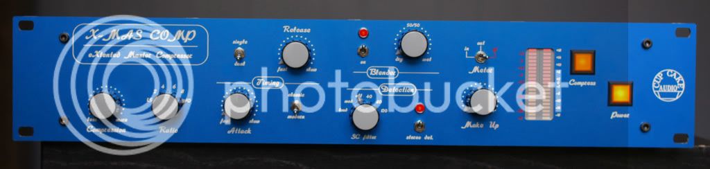
Front :
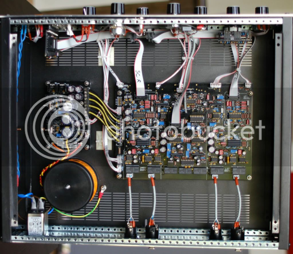
Inside :
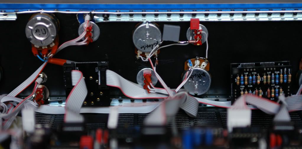
Inside front 1 :
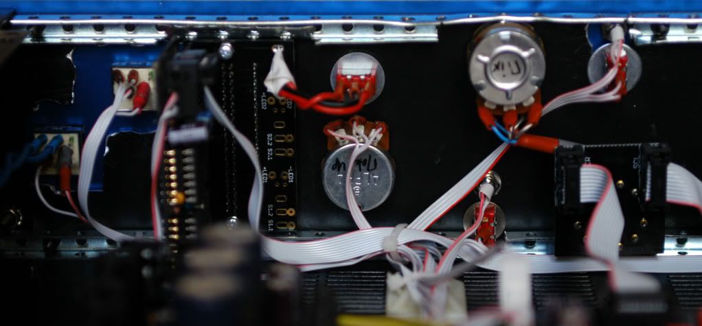
Inside front 2 :
To everyone interested by this compressor : the new features implemented by Igor are really, really great sounding !
Soft / Tight : labelled “classic / modern” in my build. It really does what it says, nothing more to say, and it really sounds great.
Single / Dual : the dual release envelop is outstanding on mix buss, you absolutly don’t need any Auto release.
Building infos :
The unit is DEAD QUIET ! Ground scheme is simple :
- center stand-off of the main PCB should be connected to the case (don’t forget to scratch the paint)
- pins 1 of XLRs connected to the main PCB (as labelled)
- and finally, case connected to Earth of the IEC.
By the way, I’ve been told by a great electronic engineer than if you have more than 2 wires, you should weave and not twist your wires, it avoid creating inductances ! Now that’s what I do with power transformers and their 4 secondary wires. I don’t know if it’s better, but I haven’t any noise problem...
I found this project to be pretty simple, even if it looks complicated ! Read the build thread, Igor’s docs and photos and you’re ready to solder. Again, nothing complicated, just beware of polarysed components (diodes and electro caps), check every thing before solder it and TAKE YOUR TIME ! I read these docs a lot while I was preparing my shopping list, it helps anticipated any futur issue, and so I didn’t have any problem, everything goes flawlessly !!! It worked at the 1st powering up.
Here is an excell doc of the BOM with EVERY THING YOU NEED to build this project :
http://www.megaupload.com/?d=4K2FOCVD
(EDIT: as MEGAUPLOAD is "dead" you can email me and I'll send you the excell file right away!)
It’s almost exclusively a Mouser shopping list, plus some things like the LED meter Ics LM3914N which needs to be ordered elsewhere (in my case Radiospares, the french RS Components). If you wanna build it with rotary switches and stepped Attack/Release, you’ll have to avoid some pots and add some rotary switches, but every caps and resistors are on the BOM. If you wanna build it with Attack/Release on pots, avoid some caps and resistors (see the Notes column).
Here is also my Mouser Cart for potted Att/Rel version :
http://www.mouser.com/ProjectManager/ProjectDetail.aspx?AccessID=82632283cc
For rotary switches version, adjust some quantities, and add or avoid some caps and resistors. You will just have to add enclosure, power transformer, IEC connector, fuse and LM3914N, and that’s it ! And you also need ribbon cable, you have the Mouser reference in the excell BOM but it’s a 100’ reel !
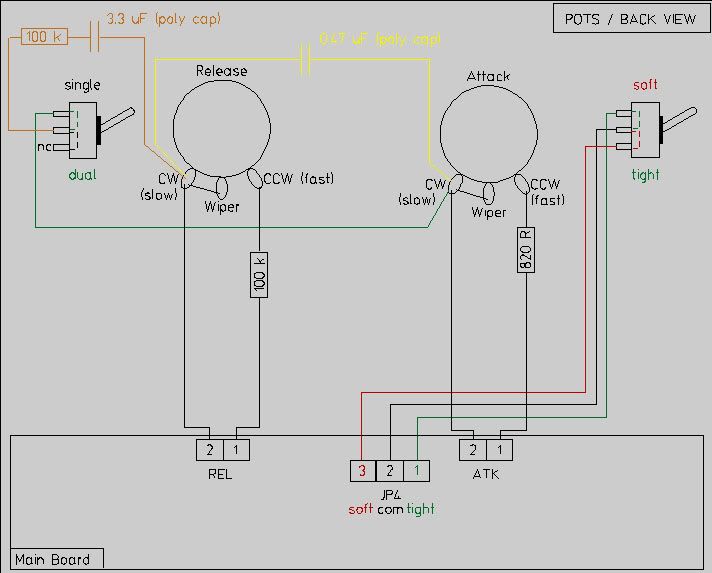
And finally, here is an “Attack/Release wiring for dummies” diagram, we never know, it could help :
OK, I think that’s it. Thanks to Igor for this wondefull project and God bless DIY.
Ben.