1176 Help

GroupDIY Audio Forum

Help Support GroupDIY Audio Forum:

This site may earn a commission from merchant affiliate links, including eBay, Amazon, and others.

RJS

Member
Joined
Aug 3, 2006
Messages
22
Hello Everyone,

I'm working on an 1176 clone using mnats’ revision J board and the BOM from Greg.

After initial power up I had input a signal and the meter would respond, however there was not output. Then I attempted the calibration using the instructions on Gyraf’s site (without a scope as I don’t have one) and now I get the signal to pass through but it's not compressing (or at least doesn’t sound like it) nor does the meter move with input.

Even the zero adjust pot has no effect on the meter. Although the needle on the meter returns to -20dB in VU mode, it stays at -7dB in GR mode. It also pegs for a instant once in a while when the unit is initially turned on.

I’m using the transformer input and wired a dpdt switch to enable the "all buttons in" function using Gyraf’s notes. The ‘all buttons in’ switch seems to compress for half of a second when switched on but then goes back to no compression.

Can anyone help? At least point me in the right direction? Do you think this is more of a calibration issue or is there something else I should be looking at? I can send pictures if that helps.


Thanks so much for any help.
Robert
 
Been a while since I did my 1176, but I'll have a crack.

If the audio passes through but the meter doesn't show anything when switched in to "output" mode there has to be something wrong with either your meter connections, the metering selector switch or the meter itself. When switched to "output" mode the meter just sits across the XLR output via a series resistor. To this end the meter has to be an AC type, or at least a DC meter with a fullwave bridge rectifier sitting across its terminals, otherwise you won't see much movement at all. The fact that the meter shows something when in "GR" mode and nothing in "output" mode makes me think that maybe your VU meter is a DC type.

The meters in my units also peg when it's turned on, so I don't necessarily think that points to anything in particular.

I'd start measuring the easy stuff first - DC supplies correct at the outputs of the power supply, all DC voltages present at the approproate points in the schematic. I'd also suggest double checking the connections and switching action of the ratio switch and output/GR switch.
 
Thanks for the reply Curtis. I tested the supply coming from the transformer and I get 28v. I also double checked the component layout on the board and the pot wiring with that on mnats's site and it looks good as far as I can tell. I'm also using a Sifam AL29, not sure if that's an AC or DC vu meter. The voltage at the meter lamp is 28v.

The needle doesn't even peg when turned on anymore.

I will post pictures so maybe someone can take a look and possibly spot an error(s).

Robert
 
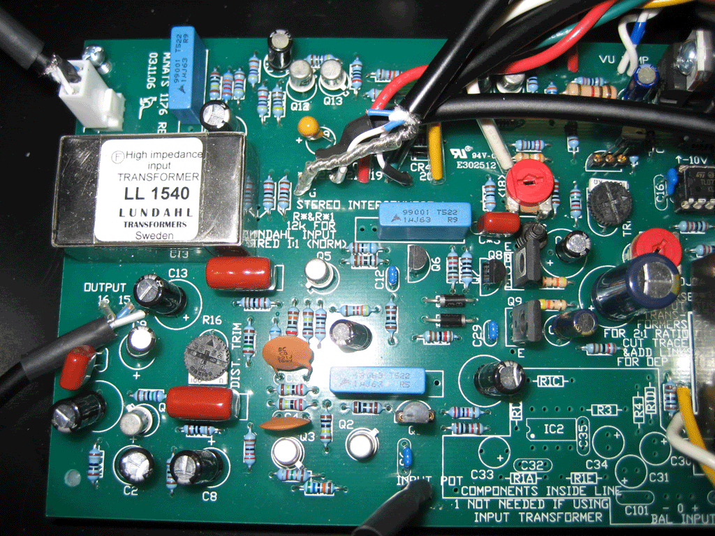
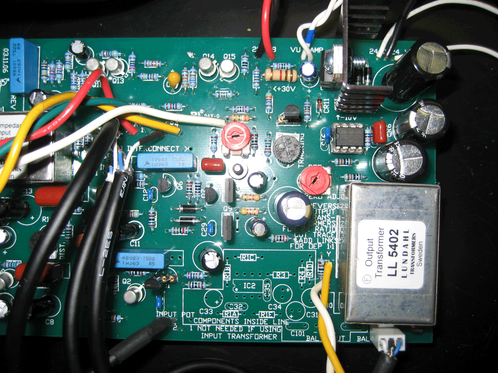
Here are pics of the board maybe someone can spot an error that I've overlooked?

BoardLeft.gif


BoardRight.gif


btw, small screw by by C*3 and Q8, fell in there while I was taking the pictures. It wasn't there when I powered up and tested. :grin:

So now, not only does the meter not register, I can no longer pass a signal through it. :sad:

I would be willing to pay someone to have a look at it and help figure out what is wrong with it? I feel since my troubleshooting skills are limited I am sort of shooting in the dark.

If anyone can help I would be most grateful.

Thanks,
Robert
 
Sorry, hard to tell from the photo's :(

I'm stabbing in the dark also, but:

Q8 and Q9 are correct, not swapped over, and the correct way around? Q8 is BD139, Q9 is BD140.

Nothing underneath the board is touching the case?

All diodes installed the right way around?

Any accidental solder bridges or bad-etched traces under the board? You may have to pull out a magnifying glass to see them all. I had to borrow a 10x jewellery eye glass to catch all the shorts on my G-SSL clones.

Dry solder joints?

Do you have access to an oscilliscope?

Have you been through the general G1176 help thread?:

http://www.groupdiy.com/index.php?topic=646

I'd take up your offer for paid help but I reckon the postage to and from Oz is probably a bit too steep to make it worthwhile. :?
 
Thanks for the reply Curtis and the offer to look at it I appreciate it. Yeah the shipping might be a bit much lol

I checked to make sure that all of the offboard wiring was making proper connections to the main board and everything is. No smoke or burning so that's good too :grin: Unfortunately I don't have a scope.

I've only scanned through the official help thread but I will have a detailed look taking it in sections since it is so huge.

I think it may be a good idea to take a break for a few days and get my thoughts together.

Robert
 
Hi Jakob,

Sorry about that. I'll post my questions in the official help thread.

Robert
 
What type of fets?,if they are 2n5457 they are in the wrong way round :roll:
see my pics here,they may help
http://www.groupdiy.com/index.php?topic=26026&highlight=
 
Back
Top