Hey guys,
I have had this idea in my head for a few years now. A few of my friends tell me it’s crazy just due to possible support type issues. I guess I am crazy cuz I don’t think it’s too big of a task to tackle.
Here’s the jist. I have successfully built line in only versions of the input channels from my ’76 API desk. I have them formatted for the monitor bucket and are pin compatible with the old IC based API 812 modules. They are a bastard size of .75" wide and 10.65” in length. I have had numerous enquiries about them but have been dragging my feet in ordering stock due to the concept mentioned here. I knew that I would eventually format them for this nice and popular 500 size and I didn’t want anybody mad who ended up with the bastard size but really wanted a normal 500 size project. The monitor size channels are really most beneficial to someone who has an actual old API board and wants to make that part of it better, like myself and Dennis(aka API) in Sweden.
Here’s what I am thinking.
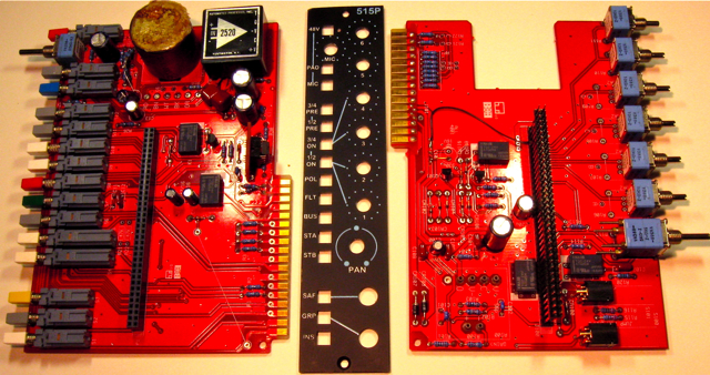
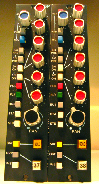
Channel faceplates will be the standard 1.5” X 5.25” size. The PCB’s will be 4.5” X 5.6”. Each channel will be made of (2) standoff sandwiched PCB’s. They are more or less the same circuit found in my console. I can explain in great detail but it may get very long.
The overall concept would be for 8 channel buckets. I would use 3mm motherboard’s with 2 oz copper, .156” card edge connectors and .156” Molex headers. Top and bottom metal would be .0625” zinc plated steel. They would be similar to the top and bottom of the 51x rack. The sides would be .125" aluminum and would be flush with the faceplate. They would be designed to bolt together, side by side. No back’s for the buckets. The backplane would be the back.
I have the input channels worked out which you can see on the pdf below. These CAD drawings are pre-lim. I start all of my layouts in AlphaCAM so I can work the faceplate, backplane and the circuit all at once. Before anyone says it, I have not labeled all of the parts properly in the silk…yet! I have not double and triple checked the circuit but am 98% sure it is solid as is. From here, all of my necessary CAD layers are exported and then imported into ARES for tracks and what not.

Anyhow, I have a lot of time into this and will gladly continue if there is any interest. It will be a huge project and I’m sure it will not be cheap or quick.
Best, Jeff
I have had this idea in my head for a few years now. A few of my friends tell me it’s crazy just due to possible support type issues. I guess I am crazy cuz I don’t think it’s too big of a task to tackle.
Here’s the jist. I have successfully built line in only versions of the input channels from my ’76 API desk. I have them formatted for the monitor bucket and are pin compatible with the old IC based API 812 modules. They are a bastard size of .75" wide and 10.65” in length. I have had numerous enquiries about them but have been dragging my feet in ordering stock due to the concept mentioned here. I knew that I would eventually format them for this nice and popular 500 size and I didn’t want anybody mad who ended up with the bastard size but really wanted a normal 500 size project. The monitor size channels are really most beneficial to someone who has an actual old API board and wants to make that part of it better, like myself and Dennis(aka API) in Sweden.
Here’s what I am thinking.
Channel faceplates will be the standard 1.5” X 5.25” size. The PCB’s will be 4.5” X 5.6”. Each channel will be made of (2) standoff sandwiched PCB’s. They are more or less the same circuit found in my console. I can explain in great detail but it may get very long.
The overall concept would be for 8 channel buckets. I would use 3mm motherboard’s with 2 oz copper, .156” card edge connectors and .156” Molex headers. Top and bottom metal would be .0625” zinc plated steel. They would be similar to the top and bottom of the 51x rack. The sides would be .125" aluminum and would be flush with the faceplate. They would be designed to bolt together, side by side. No back’s for the buckets. The backplane would be the back.
I have the input channels worked out which you can see on the pdf below. These CAD drawings are pre-lim. I start all of my layouts in AlphaCAM so I can work the faceplate, backplane and the circuit all at once. Before anyone says it, I have not labeled all of the parts properly in the silk…yet! I have not double and triple checked the circuit but am 98% sure it is solid as is. From here, all of my necessary CAD layers are exported and then imported into ARES for tracks and what not.
Anyhow, I have a lot of time into this and will gladly continue if there is any interest. It will be a huge project and I’m sure it will not be cheap or quick.
Best, Jeff
")