Calculating capacitors after bridge rectifier and before regulator.

GroupDIY Audio Forum

Help Support GroupDIY Audio Forum:

This site may earn a commission from merchant affiliate links, including eBay, Amazon, and others.

Analog_Fan

Well-known member
Joined
Mar 22, 2022
Messages
528
Location
Universe
I was watching this video:


The power supply
design for my push pull amp experiment:
Mosfet power supply.jpeg

I had my focus on "fat" capacitors for the circuit itself and forgot that i also need capacitors behind the bridge rectifier and before the "regulator".
In the above video it talks about the Vdrop of the 7805 @ 2:37.

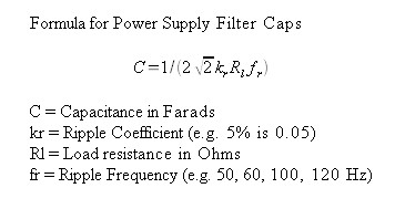
How would i apply the formula of this guy to find out the the values of the capacitors using the above mosfet circuit?

15V trafo after bridge rectifier = (15,4×1,4)−1,4 = 20,16V

If i would follow this guy:
input Volt: 20,16V - output V: 15 = 5.16V
2 x 5.16V = 10.32

using his formula:
(0,7×1,5)÷(10,32 × 50) = 0,002034884 F.
1,5 = the push pull circuit design target in Amp

Is this correct?


related to:
https://groupdiy.com/threads/a-darlington-type-audio-amplifier-idea.87389/
https://groupdiy.com/threads/amps-vs-pcb-track-width-using-to-220-package.87423/
 
I am not sure that I understand your question. The basic calculation made about power supply reservoir capacitors is regarding ripple voltage. You want to size the capacitor such that the minimum voltage does not cause the regulator to drop out of regulation. There is a simple relationship for capacitor discharge in volts per second V=I/F. The time is a simple function of mains frequency, either 50 Hz or 60 Hz, and full wave or half wave rectification.

We can solve this crudely ignoring that the cap does not discharge for the entire cycle, or half cycle. Worst case is 50Hz mains and half wave rectification. That reservoir cap is topped off every 0.02 seconds, the 1,000 uF cap in your picture (0.001F) with a 1A load would discharge 1,000 volts in one second. In 0.02 seconds it would discharge 20V. That is a lot of ripple but a 10,000 uF cap would reduce that to a more sensible 2V ripple. Full wave rectification cuts that in half to 1V ripple.

Of course these numbers are arbitrary so plug in what you need.

JR

Thank you for answer.

So basically, use a scope and keep adding capacitors until your got it stable.
But out of curiosity, i would like to know the math.

I got some RDE 4700uF, made in W. Germany, most probably older then the German unification.

RDE 4700 uF.jpeg
 
You can work it out from the approximate formula::

C x dV = I x dt

where I is the load current, dV is the ripple voltage, C is the reservoir capacitance and dT is the period of the waveform (which is 1/(2xf) for full wave rectification).

Rearranging this gives us a formula for the capacitance in terms of the desired load current, ripple voltage and mains frequency:

C = I / (dV x 2 x f) (as per the video)

The guy in the video gets the ripple frequency wrong because he forgot he has full wave rectification (He uses 50Hz but still manages to get a reasonable answer.)

For 0.5A current and a ripple of 7Vpp at 100Hz the correct capacitor values is 0.5/(7 x 100) = 740uF so you would use the next size standard value of 1000uF.

The video has several errors. The 70% capacitor factor is not needed. He is correct in allowing for diode drops but forgets that the capacitor charges up to the peak of the input voltage. And he completely ignores dissipation in the regulator.

In you case with 15V ac secondary will give a rectified dc across the reservoir cap peaking at about 20V as you said. You want 15V out so you cannot have any more the 20 - 15 = 5V peal to peak ripple on the reservoir capacitor. To achieve this at 1.5 amps load current will need a capacitance of:

C = 1.5/(5 x 100) = 3000uF

But this doe not allow for any voltage drop across the MOSFET so you probably need at least another 5V raw dc. To account for transformer losses and mains voltage variations you will probably need a 20VAC secondary transformer.

Cheers

Ian
 
Last edited:
You can work it out from the approximate formula::

C x dV = I x dt

where I is the load current, dV is the ripple voltage, C is the reservoir capacitance and dT is the period of the waveform (which is 1/(2xf) for full wave rectification).

Rearranging this gives us a formula for the capacitance in terms of the desired load current, ripple voltage and mains frequency:

C = I / (dV x 2 x f) (as per the video)

The guy in the video gets the ripple frequency wrong because he forgot he has full wave rectification (He uses 50Hz but still manages to get a reasonable answer.)

For 0.5A current and a ripple of 7Vpp at 100Hz the correct capacitor values is 0.5/(7 x 100) = 740uF so you would use the next size standard value of 1000uF.

The video has several errors. The 70% capacitor factor is not needed. He is correct in allowing for diode drops but forgets that the capacitor charges up to the peak of the input voltage. And he completely ignores dissipation in the regulator.

In you case with 15V ac secondary will give a rectified dc across the reservoir cap peaking at about 20V as you said. You want 15V out so you cannot have any more the 20 - 15 = 5V peal to peak ripple on the reservoir capacitor. To achieve this at 1.5 amps load current will need a capacitance of:

C = 1.5/(5 x 100) = 3000uF

But this doe not allow for any voltage drop across the MOSFET so you probably need at least another 5V raw dc. To account for transformer losses and mains voltage variations you will probably need a 20VAC secondary transformer.

Cheers

Ian

I'm gonna save that in text file.

using, secondary transformer is a good idea and still in time to redesign pcb.
I found a 12 AC, 7W "wall wart" recently.
To power the "Zener" circuit in the MOSFET PSU circuit or the whole opamp + zener config?

I was thinking of using 5 x 4700uF, i got some 20 of these REAL German capacitors.
https://www.gigacalculator.com/calculators/capacitor-charge-calculator.php

i got a 2 x 15V, 40VA, 10VA (uneven output) ring core, some "NOS" German ring core transformer for 7€ from the same source.
: )
Hard to find transformers offline, but i did get a 8.2 Ohm 25 watt resistor and some others.

I'm thinking of using it as "sub" woover for my pc.
 
Ripple_Calculations.jpg
 
... or take out your caliper, take the numbers from available space, then look in your wallet, and the buy the largest cap that will fit.
Formulae will find the minimum capacitance for maximum corp profit.
Dealing with low voltage, avoid 780x series, locate a low noise LDO.
 
This was an interesting article from a National Semiconductor handbook.

I happen to have an old National Semiconductor Voltage Regulator Handbook from 1975. That handbooks chapter 8 has more pages and more info. That handbook was packed full with good general information about thermal management design involving heatsinks.

JR
 
... or take out your caliper, take the numbers from available space, then look in your wallet, and the buy the largest cap that will fit.
Formulae will find the minimum capacitance for maximum corp profit.
Dealing with low voltage, avoid 780x series, locate a low noise LDO.
Actually no, this is a hifi myth
With too high capacitance to drive, diodes drive stupidly-high currents in stupidly-fast transients, spreading crud all over...
 
I happen to have an old National Semiconductor Voltage Regulator Handbook from 1975. That handbooks chapter 8 has more pages and more info. That handbook was packed full with good general information about thermal management design involving heatsinks.

JR

Someone told me not to regulate the power, this guy uses 66.000 uF for each rail.
but does filter noise from the net (i saw something in ATX pc power supply, witch i can't find now, with big a inductor and big Wima capacitors right after the 220V "cable socket.)
The Fallstad simulator reports like 33kAmp inrush current using 66.000 uF, but sometimes only 55 Amp.
Needs more a investigation, some power resistors on their way to me.

I have drawn a 3rd version of the circuit back to basics with VBE multiplier.
It's quite tricky to do it well (in simulator), i connected to input to GND,
Ideally with nothing connected or grounded it should not use or shove current or have a voltage on the output. then used +10V, -10V on the input to adjust resistors for the output.
You can make a transistor output 1 Amp or so at any voltage, i did however use a opamp on the input to raise the "line level" tot 12 V.p.p, approx.
This raises the question is voltage required to move speakers? .... or Amps?
Some car amplifiers only have 12V but can produce several "thousands" of Watts (if you look on Youtube).
 
Actually no, this is a hifi myth
With too high capacitance to drive, diodes drive stupidly-high currents in stupidly-fast transients, spreading crud all over...
Yep, that's where you can put series resistors to limit peak currents. No need to have a diode drop between transformer winding and ground, unless you need a lot of power. Unsuitable diodes can excite leakage inductance in windings, that can be hard to filter. Paralleling diodes with caps and/or resistors can reduce the effect.
Using SiC diodes/rectifiers would also reduce switching noise.
 
Last edited:
I never understood how much ripple is too much (or too little). I know that it should keep the regulator stable but other than this requirement, isn't some kind of "the less ripple the merrier" scenario?
 
It may help to model your circuit in a free circuit simulator, LTspice works good and is fast to learn.
The amount of ripple voltage your circuit can tolerate will determine how much bulk capacitance you need. If a post regulator is used you do not want to drop below the regulators own voltage drop out, or else the rectifier noise will be in the power supply output voltage.
The ripple current depends on the circuit load and the capacitors internal impedance, ESR. This creates self heating so keeping ripple current under published numbers is a good idea. Self heating would not mean immediate destruction, but shorter life of the capacitor.

I put this simple schematic together, change the values as needed.
Leakage inductance can be measured with the leads shorted on the "other" side of a transformer.
There are other loss factors in a transformer, copper resistance, AC coupling and leakage to ground, parallel and other stuff that is harder to measure. This figures in how the transformer will behave at higher frequencies that can be generated with interaction between rectifier switching speed and recovery time, and transformers reactive values etc.
Use the View > FFT function to plot harmonic output.


1716608748706.png
 
I never understood how much ripple is too much (or too little). I know that it should keep the regulator stable but other than this requirement, isn't some kind of "the less ripple the merrier" scenario?
The circuit characterization or specification is called PSRR or Power Supply Rejection Ratio. This quantifies how much power supply ripple (or whatever) shows up in the circuit's output. For op amp circuits the PSRR is typically referred to the input so PSRR reduces the PS ripple noise, and the circuit forward gain amplifies it again.

JR
 
Back
Top