Calibrating the G-SSL with THAT2181 - share thread !!!

GroupDIY Audio Forum

Help Support GroupDIY Audio Forum:

This site may earn a commission from merchant affiliate links, including eBay, Amazon, and others.
I posted some of this in another thread but realized it might be more pertinent here. I used 2181LB VCAs in mine and made the following mods:

1. In the 2150 emulation circuit I made the following changes:
- Remove the 10K resistor and replaced it with a jumper
- Replace the 3.9K resistor with a 4.99K resistor (That site says to use a 5.1K, but this is what I had on hand - close enough)
- Remove the 68 ohm resistor
- Replace the 1 Meg resistor with a 220K resistor

2. Replaced the 15K resistors with 27K resistors (unity gain mod)
3. Removed 47K resistors and added High Pass filter sidechain (mod)
4. Replaced 100K resistor connected to TL072 (pin 6 on PCB, pin 2 on schematic) with 120K
5. Replaced 2K meter resistor with a 250 ohm resistor (I custom made by soldering two 499 ohms in parallel and adding heatshrink tubing)

With this configuration, the ratios clocked in as follows:

On 2:1, 10 db of gain resulted in an increase of 5.5 db
On 4:1, 10 db of gain resulted in an increase of 2.5 db
On 10:1, 10 db of gain resulted in an increase of 0.92 db

This put my effective ratios at 1.82:1, 4.44:1 and 10.96:1. They weren't exactly matched to the ratios on the schematic, but for my tastes these were close enough.

It took me a long time to dial in the meter movement because at first it was not tracking very well at all. It was roughyly showing half of what was compressing when the resistor was a 1K meter resistor. After experimenting with a pot replacing the resistor, I found the ideal tracking at 275 ohms. I had two 499 ohms that I wired in parallel to yield about 250 ohms. The tracking is really close and is only off +/- .3 db. Close enough for my tastes.
 
Thanks for the replies.

Druedger, did you leave the 10K in place below the audio VCAs, between pins 3 and 5?

Druedger, why did you put in a 120K near the TL072?

Cheers and congrats!
 
[quote author="martthie_08"]
Druedger, why did you put in a 120K near the TL072?

calibrating the ratios for use with 2181LX VCA's[/quote]
Oh, so is this in addition to the 120 or 127K resistor to the right of the TL074? I thought that was the one for correct ratios? (It shows 127K* on the current pcb.)

You're talking now about a second one, the 100K right above the TL072, connectiong to pins 6 and 8? And you're putting 120K there, in addition to the one marked 127K*?

thanks!
 
Oh, so is this in addition to the 120 or 127K resistor to the right of the TL074? I thought that was the one for correct ratios? (It shows 127K* on the current pcb.)

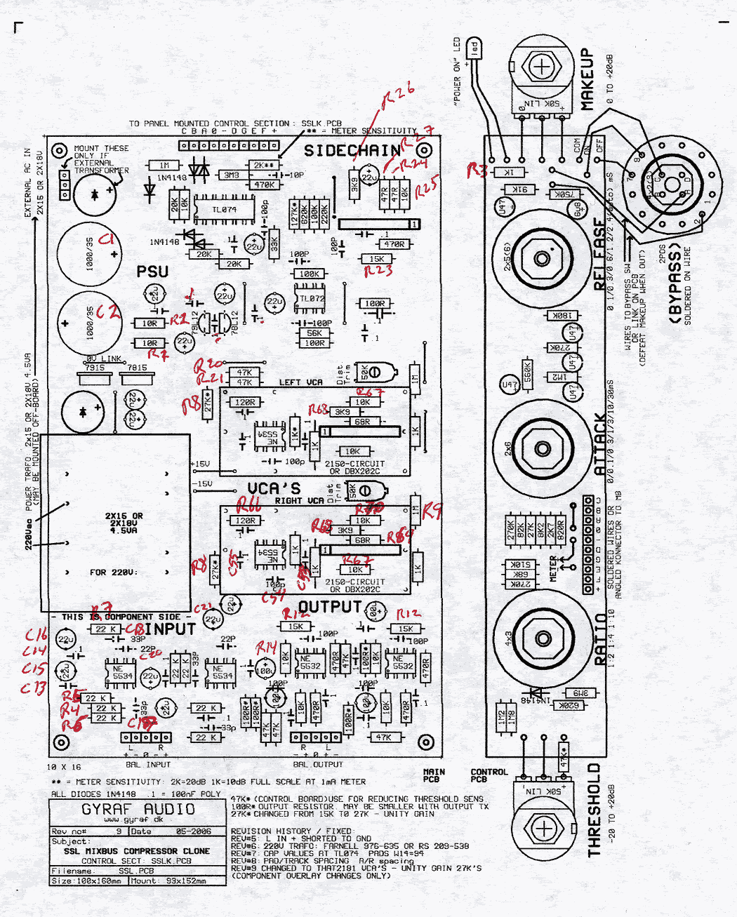
No, the resistor to the right of the TL074 (on the PCB) IS in fact the one that is going to the TL072 pin 6 on the PCB, take a look at the PCB layout.
:cool:

cheers, Marten

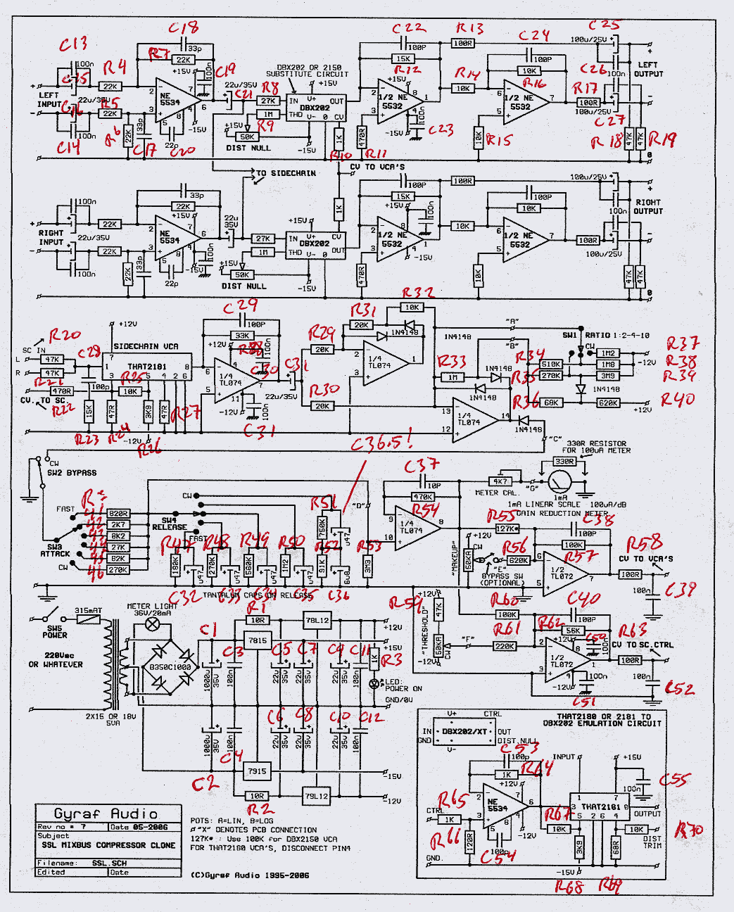
edit: Too bad the parts on the schematic are not numbered, it would make communication so much easier, any volunteers for this job??? :grin:
 
[quote author="martthie_08"]Too bad the parts on the schematic are not numbered, it would make communication so much easier, any volunteers for this job???[/quote]
Thanks. Yes, exactly. It's very confusing, combined with so many variations and mods and VCAs and different ways to adjust the ratio, etc... I have to keep looking at the traces to figure out which resistor is which. It makes corrolating parts from the schematic to the pcb very time consuming and bewildering. Then you have to start all over again next time you work on it and it's really confusing discussing parts and mods. :grin: I was planning to invent a part numbering scheme just for my own sanity. That would make troubleshooting so much easier, if we could share test points, for example. And not have to resort to pictures to identify parts.

Thanks so much for the info, everyone. My project has been worked on by two people over many months with many part changes now and it's showing the wear and tear. I must have another broken trace or pad somewhere because this one is still not working... maybe I have to build a second one so I can compare continuity and voltages with a known working board.

Cheers.
 
[quote author="martthie_08"]Too bad the parts on the schematic are not numbered, it would make communication so much easier, any volunteers for this job??? :grin:[/quote]
Yes! See here. I numbered the parts on the schematic. Haven't finished locating all of them on the layout, and I'm not very good at following the traces. :grin: Maybe others can help. Seems to me some parts are missing on the layout, but I may be mistaken.

This has already helped me troubleshooting and it would be great if we could, for example refer to the CV testing off of R10, and changing the summing resistors R20 and R21, and audio VCA resistors by number too. Other test points would be very easy to refer to by part number. Would make things much more logical and also easier to follow the schematic and the pcb.

You'll see I missed one cap so there is a C36.5 part number! :) Sorry the images are so large, I thought the message board would scale them. I'm planning to put these on the Twin-x server but I'm having technical problems with that server.
GSSLSchemNumberParts.gif
GSSLLayoutNumberParts.gif
 
[quote author="tommypiper"]Druedger, did you leave the 10K in place below the audio VCAs, between pins 3 and 5?

Druedger, why did you put in a 120K near the TL072?
[/quote]

You probably already have your answer, but the 10K between pins 3 and 5 is replaced with a jumper wire. Essentially it goes to 0 ohms.

The 120K was to get the right ratio settings. I'm still tewaking this on my 2nd unit and will probably get the exact ratio after running it trhough a pot to dial in the exact resistance. I should have an update on this within the next couple of days.

Sorry for the delay. I've been slammed recently.
 
I am really confused now after reading through this thread. When I decided to build the Gssl comp I read the entire 117 pages of the Help thread....and I concluded I would build it with 2181's. Now that it is together I was planning on putting in the chips and calibrating it, so I came to this thread, which has me worried.

What I had originally understood from the help thread is that if you use the pre trimmed 2180's you leave out the items connected to pin 4, but if you use 2181's you build the boards exactly as they are. So I followed all the silkscreening and the schematic.

But now I am confused from reading this thread, it seems to be more of a MODification thread than a calibration thread? Should I have left out or changed some parts?? Is this right, or can I use it as I've built it or will it have problems? It seems everybody has done something different here, and being a Newbie hopefully you can see where I'm confused. I should also mention that I have also added on gregs/steffans sidechain board to the compressor if that makes a difference.
 
hi there.
I just finished my first SSL and it's now time to calibrate the ratio.
I am sligthly confused as it looks like it's behaving in a bit of a weird way..
when i have got the threshold all the way CCW (so at the minimum in order to affect as much signal as possible) the Ratios behave in the opposite way:
2:1 compresses more that 4:1 (on the meter it shows less dB compressions and the output is louder at 4:1 that it is at 2:1)
4:1 compresses more than 10:1
is this normal?
I have done the mods on the AUDIO VCAs and tamed the threshold using a 47K resistor.
do I need to take the 47 ohm resistor on the sidechain VCA out and connect PIN4 to ground?do I also need to take the 10K resistor off Pin 4 and 5?

it's a bit weird I can't get my head around this "opposite compression" I am experiencing with the unit and I could not find anyone on the forum that had the same problem...anyone there that could throw their 2 cents in?
I read Keith comment on how to adjust the ratio but still I cannot figure it out the reason why the threshold is behaving this way--IS IT THE CASE the compressor is working "after infinity point"?
many thanks in advance!!!
 
Your behaivor is normal. Jakob gave a really good explanation somewhere in the GSSL help thread. In summary, the GSSL attempts to average the amount of compression. This results in less dramatic change from ratio to ratio.

Just as a hypothetical example, if you're compresing 3dB at 10:1, if you switch to 2:1, you're gain reduction will inscrease to maybe 4dB or 5dB.
 
thank you very much Greg!
what about the mods on the 2181 VCA?do I need to connect in the same way I connected the audio VCAs?
and I mean:
do I need to take the 47 ohm resistor on the sidechain VCA out and connect PIN4 to ground?do I also need to take the 10K resistor off Pin 4 and 5?

thanks in advance!
 
I've never used the 2181 so I don't want to comment and give you bad information. I know there's a table around here with all the info you seek. I'm only familiar with the 202, 2150, and 2180.
 
there are some "mods" to the circuit that need to be done to get things workng correctly with the 2181. These are pretty much the changes that i used, although i omitted the 120k summing resistors as i used the sidechain. These are quoted from one of "Fucaney's" emails. They are according to the specs from That corporation for using 2181 VCA's

took out the 68R next to VCAs

- replaced the 10K with the jumper next to the VCAs

- deleted the 10K resistor between pins 3 and 5 of the VCAs

- replaced the 3.9K resistor with the 5.1K next to the VCAs

- replaced the 1M resistor with the 220K

- changed the 100K to 120K on the right of the TL074

Ian
 
just a quick note: I had a stuffed PCB according to the original schematics that needed to be racked up and I did the calibration described earlier in this thread. I listened back 20 minutes later, with all resistors changed and the difference is dramatic! Much more defined sound, less distortion going on, so much nicer!.

:guinness: and cheers, Marten
 
Which version of the chip are you using - is the higher distortion chip acceptable (maybe in sidechain only?) or should the lowest distortion chip be used throuhout :?:
 
Hi there !
Really interesting subject...BUT : I didn't really understand the mods in the sidechain using 2181LA....
Leavin the both 47R , leavin the 10K , and grounding pin 4 of the sidechain VCA????
Am I correct???
thx for help!
 
hi,

i'm not a specialist, but according to :
http://homepage.mac.com/marten.thielges/gssl/calibration.html

with taht 2181LA :

4. remove the 10k resistor between VCA pins 5 and 3 on both sidechain and signal path VCA's.
5. For the signal path VCA's, change the 3K9 resistor from VCA pin 5 to V- to a 5K1 resistor. (only for signal path VCA - leave 3K9 on the sidechain)
6. For the sidechain VCA, remove the 47R resistor that connects leg 4 to ground (i.e. do not connect to ground - leave it as is)

hope it helps.
 
Back
Top