


sonicwarrior
Well-known member
Things started out in the synthesizerforum.de when someone
pointed out to the Gyraf Calrec EQ design.
As I'm in need of an equalizer I jumped on that and started a groupbuy for the not-so-easy-to-get components.
Then I've found out that Purusha makes also cases if there is enough interest, so I started with a FPD design from Frank (nrgrecording) and made some minor changes.
To be able to quickly compare the sound without a channel I definately wanted band-bypass switches which would also make center detent 10k pots obsolete so that you can operate smoother close to the midth point (which you IMO cannot with a center detent pot).
You can have the pot position everywhere and switch the band on and off to compare.
Here is how it goes:
http://www.groupdiy.com/index.php?topic=17603
Here is the thread with my FPD design:
http://www.groupdiy.com/index.php?topic=17863
And what Purusha made of it:
http://www.groupdiy.com/index.php?topic=18074
But when we both were working on the frontpanel design we
recognized that the PCB layout has some limitations:
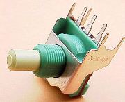
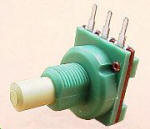
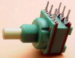
1. I think the Omeg series PC16ECO pot with 3 pins is not as stable as the series BR16ECO:
In comparison the PC16ECO pot:
But it should be possible to use them as well.
The dual pots are the series PC2G16ECO which should be stable enough with 6 pins :
You can of course use compatible pots like the 16 mm metal can series from Omeg, or compatible Alpha pots.
2. The shelve switches - when PCB mounted - are located to close to the pots (Hi freq / Lo db).
3. The PCB set should be layout for the sequence
Lo, Lo-Mid, Hi-Mid, Hi in 19" rack format and not for a mixer layout like the original.
You can of course use the current layout mirrored but it's not perfect and may lead to confusion (and therefore errors) because of the mirroring.
4. Eventually:
Separate frontpanel and "backend" PCBs.
That would make the cantilever problem easier when mounting the PCB through the pots on the frontpanel.
5. Direct support for the band-bypass switches (but not PCB mounted because there is not enough place on the frontpanel for them).
6. Eventually:
Using a 10k lin pot with included push switch (for the band-bypass).
Pros:
- Frontpanel layout can be made for both people that want and people that don't want the band-bypass switches. The PCB should support both.
Contras:
- There is IMO no such switch (PCB mountable) from Omeg
(only pots with rotary switch for power on-off).
7. Holes for spacers if someone doesn't want to use SPUN switches and PCB mounted pots (Alpha/Omeg, don't know if there are others with 2.54 mm pin spacing and 100k dual rev-log values).
I personally think it's a pain to solder 4 pole switches in "free hand".
But spacers may also be used to have a more stable connection and to solve the cantilever problem.
8. A double sided PCB may be smaller and may make routing easier.
Edit: As you can see in my second post here: The first PCB of the re-design is already finished, so please no further comments about the 8 points listed here.
pointed out to the Gyraf Calrec EQ design.
As I'm in need of an equalizer I jumped on that and started a groupbuy for the not-so-easy-to-get components.
Then I've found out that Purusha makes also cases if there is enough interest, so I started with a FPD design from Frank (nrgrecording) and made some minor changes.
To be able to quickly compare the sound without a channel I definately wanted band-bypass switches which would also make center detent 10k pots obsolete so that you can operate smoother close to the midth point (which you IMO cannot with a center detent pot).
You can have the pot position everywhere and switch the band on and off to compare.
Here is how it goes:
http://www.groupdiy.com/index.php?topic=17603
Here is the thread with my FPD design:
http://www.groupdiy.com/index.php?topic=17863
And what Purusha made of it:
http://www.groupdiy.com/index.php?topic=18074
But when we both were working on the frontpanel design we
recognized that the PCB layout has some limitations:
1. I think the Omeg series PC16ECO pot with 3 pins is not as stable as the series BR16ECO:
In comparison the PC16ECO pot:
But it should be possible to use them as well.
The dual pots are the series PC2G16ECO which should be stable enough with 6 pins :
You can of course use compatible pots like the 16 mm metal can series from Omeg, or compatible Alpha pots.
2. The shelve switches - when PCB mounted - are located to close to the pots (Hi freq / Lo db).
3. The PCB set should be layout for the sequence
Lo, Lo-Mid, Hi-Mid, Hi in 19" rack format and not for a mixer layout like the original.
You can of course use the current layout mirrored but it's not perfect and may lead to confusion (and therefore errors) because of the mirroring.
4. Eventually:
Separate frontpanel and "backend" PCBs.
That would make the cantilever problem easier when mounting the PCB through the pots on the frontpanel.
5. Direct support for the band-bypass switches (but not PCB mounted because there is not enough place on the frontpanel for them).
6. Eventually:
Using a 10k lin pot with included push switch (for the band-bypass).
Pros:
- Frontpanel layout can be made for both people that want and people that don't want the band-bypass switches. The PCB should support both.
Contras:
- There is IMO no such switch (PCB mountable) from Omeg
(only pots with rotary switch for power on-off).
7. Holes for spacers if someone doesn't want to use SPUN switches and PCB mounted pots (Alpha/Omeg, don't know if there are others with 2.54 mm pin spacing and 100k dual rev-log values).
I personally think it's a pain to solder 4 pole switches in "free hand".
But spacers may also be used to have a more stable connection and to solve the cantilever problem.
8. A double sided PCB may be smaller and may make routing easier.
Edit: As you can see in my second post here: The first PCB of the re-design is already finished, so please no further comments about the 8 points listed here.
") .
.