differences of noise coupling between transformers (G9 B+ problem solved)

GroupDIY Audio Forum

Help Support GroupDIY Audio Forum:

This site may earn a commission from merchant affiliate links, including eBay, Amazon, and others.

Kingston

Well-known member
Joined
Nov 1, 2005
Messages
3,718
Location
Helsinki, Finland
Hi people,

I've been recently doing shootouts between output transformers on the G9 preamp and running all kinds of tests with them as a learning experience. I now ran into an oddity I can't explain and would like to learn what's going on.

First some data,

B+ = 245.2VDC (0.4mVAC ripple, or basically as accurate as my fluke meter gets)
Heaters = 12.25VDC (2.9mVAC ripple)
No phantom

This is the preamp noise floor on the pictures. The top one is Edcor XSM 10K/600 (hacked to 2:1), and below is Lundahl LL5402 (2:1), both at the exact same gain, matched as accurate as possible (both transformers tested on two channels and they are exactly the same).

edcorandlundahlhum.png


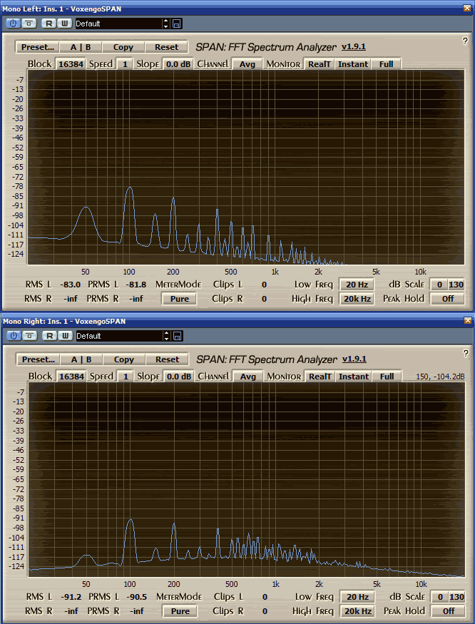
First of all, let's ignore the 50hz peak. I can almost completely remove that by optimal placement of the transformers (PSU or audio) inside the case (tested and proven).

But that 100hz peak! How come such a massive difference?

The oddest thing is that it will not move when I change gain. It's fixed at those exact points, no matter how the preamp is set. It won't change with different tubes. Yes, I realise this type of noise comes from points after the rectifiers, but my power is clean.

One last detail,
the peak seems to be at about 30dB above the general transformer noise floor on both cases. Lundahl noise floor is lower so the peak is also lower. What is this a clue of?

What could this noise be?

Regards,
Mike
 
You have peaks  at:
50 100 150 200 250 300 350 400 450 500.

Moreover, 100 200 and 400 are bigger.

Do you still have these values if you shield or move far away the PSU transformer(s), maybe outside the case?

Seems like the even & odd harmonics of 50 Hz hum, amplified..

 
1954U1 said:
Do you still have these values if you shield or move far away the PSU transformer(s), maybe outside the case?

Seems like the even & odd harmonics of 50 Hz hum, amplified..

Like I said, the 100hz peak doesn't move, no matter where the transformers are, or how the preamp is set. They stay at those exact points. That would already hint that it gets coupled at the output stage, but that shouldn't be possible with those clean power rails.

moving any of the transformers *only* affect the one single 50hz peak, not the multiples(exactly as it should do). Everything else is after the rectification. The main point of interest here is just that 100hz peak, which should not be there, based on the ripple measurements.

I don't understand where is comes from, and why the output transformers have such large effect on it.
 
I was suggesting that the 50Hz can be picked up not only by the audio output transformers [-> 50Hz gone when you change their placement vs the PSU trans],
but also by some other component, and then their harmonics amplified by V2..

Dont know if it even can happen, my knowledge is not at all deep, only a try..
 
B+ = 245.2VDC (0.4mVAC ripple, or basically as accurate as my fluke meter gets)

Never trust a multimeter's AC measurement if there is lots of DC present. At least my cheap multimeter goes nuts. Oscilloscope is needed in my experience. The power supply _could_ be that quiet, but you don't know yet.

The measurements look soooooo much like dirty power that I would at least try some cheap tricks like doubling the value of R37 just for a moment, or taking out tubes for a moment from _the other channel_ (this will give you cleaner power too). If these have no effect then we have to look for more elaborate explanations.


Jonte Knif said:
Never trust a multimeter's AC measurement if there is lots of DC present. At least my cheap multimeter goes nuts. Oscilloscope is needed in my experience. The power supply _could_ be that quiet, but you don't know yet.

Yes indeed dirty power would be the obvious explanation, and something that I had hoped it would be: easy fixes! I'll keep mucking around. Thing is, I have 470uF PSU caps here already...

I used to only have a cheap multimeter, and learned those lessons. The one I have now is Fluke 179, which I understand is some kind of workhorse standard, and can be trusted. Or maybe not!  :eek: That's not good.

The reason for this thread, and the odd thing I could not understand is the very large difference between the transformers. It would be simple to explain 50hz coupling with inadequate shields, but the 100hz...
 
Hi,

Kingston said:
A picture is worth a thousand words. Look you did see the first post, didn't you? No room for confusion here.

Sure, and that pic says more hum than noise (as in the thread title) to me.


(and I had no idea there were standardized semantics for this)

It's just a suggestion to avoid confusion (in general, 'noise' is often used for all kinds of unwanted signals); specifying helps to discuss & to tackle them.

And please note I don't want to be some kind of semantics-police, just suggesting.
I'll adapt my previous post to better reflect this.

Best regards,

  Peter
 
clintrubber said:
Sure, and that pic says more hum than noise (as in the thread title) to me.

[semantics alert]

with my limited experience, I've mostly seen hum used as describing a pure 50/60hz sine, which nearly always ends up with discussion on shielding and transformer orientation or general positioning. None of that here, at least in amounts that would ever bother me.

Then we have the multiples after rectification, which in turn invites discussion on dirty power, bad tubes, shorted PCBs and bad solder joints. "Buzz" or the more general "Noise" in my dictionary.

So what we have here is "Humnbuzz". And that's why I provided the picture, because there are no clearly defined semantics here. These descriptions might even vary quite a bit internationally.

[/semantics alert]
 
I prefer & suggest to reserve 'noise' for either all things hissy (like thermal noise and shot noise) or for the type of music  ;)

Just as for instance I'd like to see a 100% use of the term 'signal polarity' when various people use 'phase' for that switch on a micpre, etc, I realize these are & can just be nothing more than personal preferences  ;)


[ wiki alert ]

Electronic noise

Electronic noise exists in all circuits and devices as a result of thermal noise, also referred to as Johnson Noise. Semiconductor devices can also contribute flicker noise and generation-recombination noise. In any electronic circuit, there exist random variations in current or voltage caused by the random movement of the electrons carrying the current as they are jolted around by thermal energy. Lower temperature results in lower thermal noise. This same phenomenon limits the minimum signal level that any radio receiver can usefully respond to, because there will always be a small but significant amount of thermal noise arising in its input circuits. This is why radio telescopes, which search for very low levels of signal from stars, use front-end low-noise amplifier circuits, usually mounted on the aerial dish, and cooled with liquid nitrogen.

[/ wiki alert ]

Bye & enough, back now to the removal of the unwanted spectral components in your graphs,

  Peter
 
Samuel Groner said:
What's your source when running these tests?

Samuel

RME HDSP 50ohm impedance XLR I/O to G9 inputs (mic or line), or 100ohm resistors terminated to ground on the input. None make any difference on that 100hz & multiples on the picture. It seems fixed at that -78dB point on edcor, and -91dB on lundahl.

Couple of more tests I've now done:

1. R37 filtering resistor to 5k (with B+ now at 180VDC). no difference.
2. yanking off tubes from one of the channels. no difference.
3. quickly removing heater regulation (I have it on molex connector), and the 100hz will not budge.

Can dirty power be ruled out now?
 
What happens when you turn the power off?  Does the noise go away while the unit continues to amplify for a moment?  If so, it's a power issue.  If not...
 
Did you try to swap the transformers on channels?
I've not understood from your 1st post..

I say this, because Edcor [-78 db] is not shielded, and Lundahl [-91dB] I think is shielded..

Anyway, another ultra-quick test would be to slip off the mu-can from the Lundahl, I dont know if its possible..
 
What happens with a floating source resistor or shorted (pin 2 + 3) input? Where's the rectifier located? These can be nastier than the power transformer from time to time. And make sure it ain't any surrounding gear causing the hum.

Samuel
 
tommypiper said:
What happens when you turn the power off?  Does the noise go away while the unit continues to amplify for a moment?  If so, it's a power issue.  If not...

ok that rules out a lot of stuff. it's definitely a power issue. All the problematic areas go away immediately as I turn off power.

1954U1 said:
Did you try to swap the transformers on channels?
I've not understood from your 1st post..

I say this, because Edcor [-78 db] is not shielded, and Lundahl [-91dB] I think is shielded..

Anyway, another ultra-quick test would be to slip off the mu-can from the Lundahl, I dont know if its possible..

Yes I tested on lots of tubes, and with several identical transformers, on two channels.

Furthermore, I didn't know it was possible to receive/induce any of the post rectification 100hz noise magnetically.
 
Samuel Groner said:
What happens with a floating source resistor or shorted (pin 2 + 3) input? Where's the rectifier located? These can be nastier than the power transformer from time to time. And make sure it ain't any surrounding gear causing the hum.

Samuel

Sorry if I didn't write it clearly enough already, the floating source resistor, or shorted pin input makes no difference here.

And now I can already definitely say it's a power issue.

There are 3 bridge rectifiers on the standard G9 pcb (for B+, heaters and phantom separately), located on the "PSU filtering area" of the PCB. I actually already bumped into a very similar problem on another gyraf PCB, the GSSL. moving it all  (rect, filter caps, reg) out of the audio PCB solved it completely.

Maybe I should try it here? What is theoretically the biggest culprit here? the rectifiers, or all the PSU components combined? moving it out of the audio PCB is not a problem for me.

I can't say I'm a big fan of "all-in-one" tube PCBs, because troubleshoot is so difficult. I've only done p2p tube projects this far.
 
Kingston said:
Furthermore, I didn't know it was possible to receive/induce any of the post rectification 100hz noise magnetically.

Me too,.
but if I were you, before doing major works, I'd quickly test with a thick shield between the PSU transformer and the audio PCB, or move the transf outside and see what happens..
just to rule out the PSU transformer's electromagnetically induced hum.
 
Its nor something nearby like your computer is it.....just a thought Iv had similar probs in the past turn out to be something really silly....best of luck
 

Latest posts

Back
Top