Discrete preamp design

GroupDIY Audio Forum

Help Support GroupDIY Audio Forum:

This site may earn a commission from merchant affiliate links, including eBay, Amazon, and others.

efinque

Well-known member
Joined
Jan 3, 2018
Messages
368
Sup GDIY,

I know similar discussions exist but I couldn't find anything that made sense to me.

Anyway, having built several DIY kits with opamps I decided to bite the bullet and try to design my own preamp. I've been breadboarding for a couple of days, then I ran into a problem while designing and prototyping a discrete preamp.

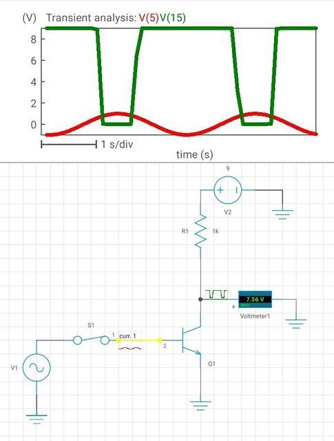
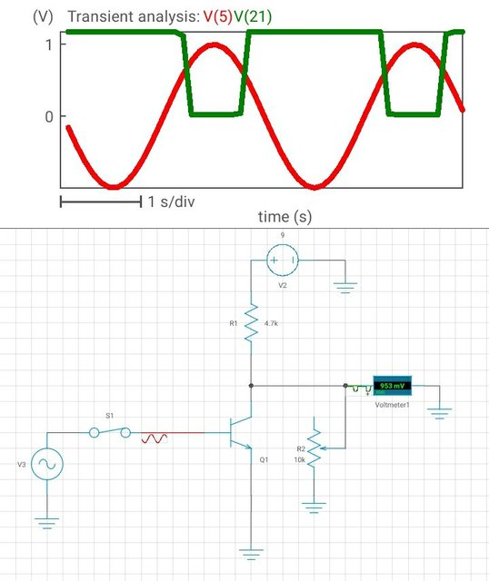
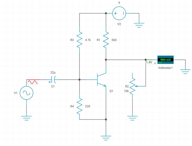
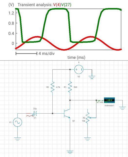
Here's the schematic :

pre.jpg


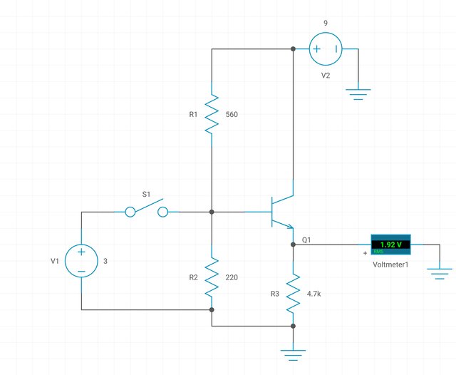
The tutorial from which I copied it from used a coupling capacitor in the input, is there a "standard" value for this?

I used a 3V CR battery (V1) to switch the transistor. V2 is a 9V battery.

Now, the problem is I get 2,02V output in my DMM when V1 isn't connected and 2,03V when it is so in theory it's working but I'm not sure it's safe to plug any sound sources or headphones into it.

I reckon I should change the resistors values but I don't know where to start, are there any rules of thumb to this?

EDA simulations showed me a PNP transistor is easier to design with, is this true? I only had one, a BC547 which is NPN, should I go straight for an opamp such as NE5532?

I also read about biasing.. If I understood correctly it takes place in the node between R1-R2 but I didn't quite grasp the concept.

Thanks in advance,

-ef
 
So with S1 open, you have 9V*(220/(220+560)) = 2.5V sitting on the base of the BJT. You'll lose 1 junction between the base and the emitter, which is ~2V that you see on the emitter.

So when you connect the 3V battery, you are trying to force 3V DC on a node that already has 2.5V, so which 'wins'?

This is why the capacitor is needed: the cap will form a high pass filter with R2 (in parallel with R1), which is ~150 ohms. You pick the lowest frequency you want to pass through, say 80Hz, which means you need about 13uF, so you could use 22uF as the next biggest standard value.
Yeah I just realized 3>2,03 but at least there's something happening. I thought it had something to do with the resistors and the shunt to ground decreasing the voltage.

I'll try the coupling capacitor later.

Thanks for the quick reply.
 
Your circuit is an emitter follower buffer, without something to buffer, so doesn´t make much sense to me?
If you´d swap the CR battery for an audio signal source via an adequate coupling cap it would work as a buffer (how
it is often used at the output of discrete preamps...)

Some concepts you should become acquainted with:

Basic transistor circuits
Input/output (also called source/load) impedance
Negative feedback
Noise generation and how to minimize it
Transformer function incl. Optimum Source Impedance

It would probably much easier for a beginner to start with opamps (it was for me)

(y)
Thanks for the reply.

I though starting out with transistors would make sense since opamps only contain a bunch of them..

I did breadboard a rather noisy NOT gate, it was a common emitter circuit where the output was 9V when there was no base voltage and near zero when there was, so I guess I'm on the right track (one application would be like, a beeper turns on when a door is open and turns off when it isn't)
 
Here's the simulation of the common emitter amplifier circuit :

Screenshot-20240329-094845-2.jpg


As you can see it's inverting. The red line is a 1V AC sine wave, the green line is the output.

Now, this is what they call a class A amplifier right? Because the transistor is conducting during negative cycles. It has a lot of gain too, does changing R1 affect the output voltage?

And does it benefit from a coupling capacitor?
 
Yes, it´s an "inverting amplifier", but it amplifies with full open loop gain and hits the supply rails with every wave cycle...
With input signal lower than one diode drop (base emitter voltage) the transistor is not conducting at all and basically an open circuit and the output sees 9V via R1, if the signal exceeds the base emitter voltage the transistor starts to conduct but because of the high gain it conducts so much that it literally shorts the output to ground. That´s the squarewave you seeing. You could call it a "fuzz"...(s.below some of the simplest pedals you could build)

So for making it a linear audio amplifier you need in and out coupling caps, biasing and an emitter resistor. Read up on "common emitter amplifier".

1711720236224.png
 
In my latest circuit (post #6) I put a 10k trimmer to ground (before the voltmeter) and I got the output within reasonable values, from 0,2V to 8,8V.

I was trying to put it in series instead.

Would this make for a simple headphone amplifier?
 
Now, this is what they call a class A amplifier right? Because the transistor is conducting during negative cycles. It has a lot of gain too, does changing R1 affect the output voltage?
You need the biasing components.

With a grounded emitter, the BJT cannot be 'on' until the input signal reaches a diode threshold (~0.6V). Since your input signal is moving between ground and 2V, nothing will happen until it reaches ~0.6V and then the output will suddenly drop down, as the current through the BJT causes a voltage drop across R1.

If you want to see a 'clean' output waveform, you need the biasing resistors from the first picture, and a coupling capacitor. If you want the simplest circuit that simulates an amplifier, you need to adjust the DC offset of the voltage source to be roughly half of 9V (~4.5V) so that the input signal 'rides' between 3.5V and 5.5V. This will keep the BJT always conducting and you should see a clean waveform at the output.

R1 helps set the voltage gain of the amplifier: there are a million web sites that explain how to bias and calculate all of the resistances, but this one is a good starting point. Or you can Google, "common emitter bjt equations".
 
Here's the current circuit with the trimmer and the input (red) and output (green) waveforms.

Screenshot-20240330-104333-2.jpg

Adjusting R2 sets the output voltage, I set it around 1V to match with the AC input.

EDIT : during a recent test I ran program material into the circuit and I noticed a positive change in the transistor temperature, is this due to switching? In another circuit (I can't remember which) the battery and the alligator clips attached to it got really hot too.

EDIT 2 : R1 in my breadboard was actually 220R.. apologies for that.
 
Last edited:
Without something biasing the base and without anything in the emitter this is going to act like a fuzz pedal but with turn on problems.
If your looking to create a real preamp then maybe something like a two stage design with a volume control in between (optional tone stack). Just sub a volume pot in for RL.
https://blog.mbedded.ninja/electronics/circuit-design/bjt-common-emitter-amplifier/
I just tested it with a 5V square wave (50% duty cycle) from an Arduino Uno using the tone library.

I got it working complete with volume control and everything. Now, to get it working with small signals is another thing..
 
Square waves are not going to tell you anything like clipping. You need a sine wave. Grab a 3.5mm cable and from your computer use an audio generator. I use Signal Scope Pro on all my macs because I can make any waveform I want. I also use an AudioQuest DragonFly (Black, Red or Cobalt) to output my signal as it has an analog volume control so I don't loose resolution (plus I designed them). If you have a DAW interface that works as well and with software like Signal Scope Pro you can also look at the outcome of the amplifier.
FYI on a positive note I applaud what you are doing. I think the opamp is over used when you can do so much better without all that feedback. Feedback kills space and simple things like buffers with unity gain opamps is just silly. There is a reason Boss and others use a single transistor buffer circuit. It just sounds better.
 
Are you testing the exact circuit as depicted in the simulator? If wired that way, you will not get any appreciable clean signal out of it. Notice your green and red signals in the trace bear no resemblance to each other. In fact, fo the vast majority of the input signal, the transistor is just turned off, and the output just sits at the upper rail. A typical common-emitter amplifier will just give you a larger version of the input (although inverted).

OTOH, if you are trying to get a distortion effect or something similar, that is another thing.
 
Thanks for the input!

I just tested the circuit with a 22uF coupling capacitor and a 4.7kOhm bias resistor, it works with a 5V square wave from the Arduino.

EDIT : I noticed the tone changes when I shunt the base to ground using a 220R resistor.. is this due to the coupling capacitor and the resistor forming a HPF?
 
Last edited:
I took some video footage of the circuit running the Arduino serial plotter.

The waveform is a 100Hz square wave at 5V. The signal is being monitored from the amplifier output via a 47kOhm resistor using the
Code:
analogRead
function.

View attachment VID_20240401_145740.mp4

EDIT : I think I need a sine wave generator.. but they're mad expensive. So far I've been using Audacity.

EDIT 2 : here's the complete schematic, just replace V1 with a square wave:

test.jpg


EDIT 3 : without the amplifier, the output is significantly lower, I don't have scientific data to back this up though.. use it as a synth buffer?

EDIT 4 : it works with line level signals.. however the output is distorted. I just removed R4 and bam.

EDIT 5 : here's the complete schematic/simulation :

Screenshot-20240401-192012-2.jpg
 
Last edited:
I just ran some tests.. here's a spectrum analysis of a 1kHz sine wave.

pre-thd.png


According to my calculations it has THD of 2,25%.

I also played some program material in headphones too, this thing is LOUD and very distorted, so there's room to improve.
 
Last edited:
C1 in your first schematic is (very likely) backwards. The '+' side of the cap needs to face the higher DC voltage.

R4 at 220 ohm is too low: the voltage at the base is (220/(220+4700))*9V = 0.4 volts, which means the transistor isn't turned on when sitting idle. Your simulation plots show the circuit turning a sine wave into a square wave, which isn't what an 'ideal' amplifier should do. :) You also (likely) need a coupling capacitor at the collector as otherwise the output won't swing around ground.

I really suggest you start with a known working circuit and tinker from there. The link I posted before has a circuit with (common) starting values: even though the supply is 12V and yours is 9V, it should still work properly. You can omit CE (the emitter bypass cap) for your first experiments.

amplifier-amp31.gif
Oddly familiar-looking schematic, I believe it's the one I tried to copy. It's from electronic-tutorials.ws right?

Mine uses what they call fixed base biasing which doesn't use the 3,6k and the 220R resistors.
 
I noticed a positive change in the transistor temperature

You are building that circuit (from post #10) with real components, not just in simulation? That circuit will likely damage the transistor and the signal source.
A base-emitter junction is like a diode, it has a "knee" in the voltage vs. current curve, until around 0.5V almost no current will flow into the base, then the junction begins to conduct and at around 0.7V the voltage will stop rising substantially no matter how much current you supply. That will cause heavy heating in the transistor if the signal source can supply a lot of current, and can overheat the signal source as well.

this thing is LOUD and very distorted, so there's room to improve.

I guess it can be fun to play around with something with no idea what is going on and try to deduce how it works, but if you goal is to make an actual working circuit it would be much faster to begin with an introductory text on how transistors operate, and how they are used in simple circuits to avoid things which cannot work at all like you want and may damage your components (such as the circuit in post #10).
 

Latest posts

Back
Top