Note, this is based from my experience building the Drips La2a Version 3 and other peoples experience may vary so take it with a grain of salt.
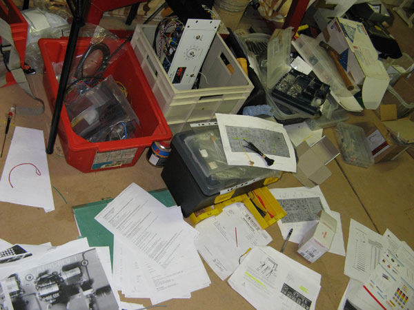
The lab. Working up to 6-10am these past few weeks trying to get these beasts completed. Garage is not the best place to do DIY I have realised. Frrrrreeeezing! 8)
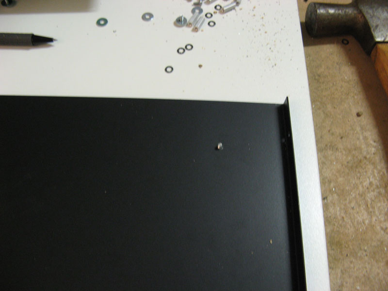
Clear table is best to prevent scratching your case... eh.
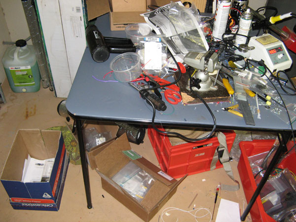
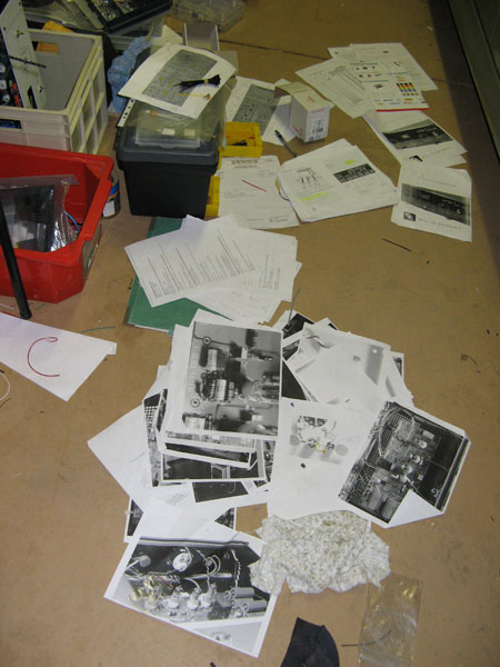
Printed pics to reference from.
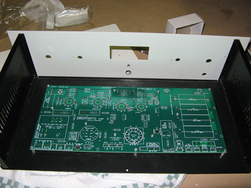
Preparing case for Drips pcb board. For setting PCB mount, best to drill a hole one at a time then re-align PCB, mark next hole then drill and so on.
eg.
Push bolt thru bottom case so that it portrudes and you can align your PCB board using that portruding bolt.
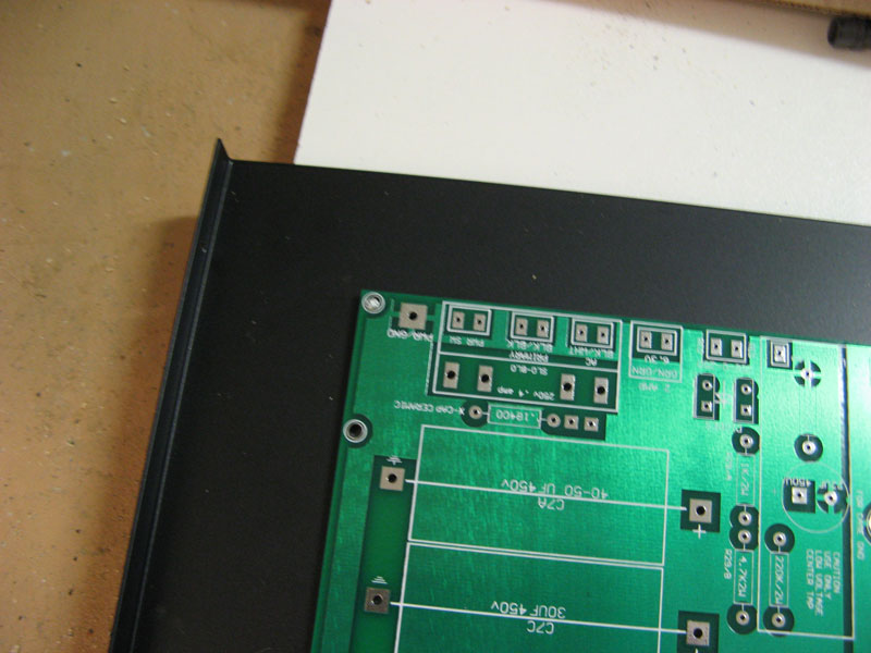
Place PCB on top of bolt and then mark the next hole while pushing the board flat since I had a slight warp on my board which straightens up once the PCB board is mounted properly.
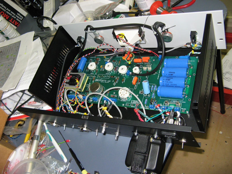
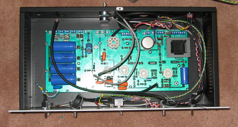
Solder components
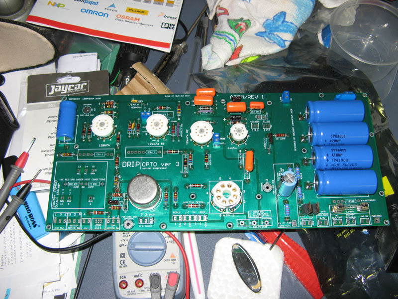
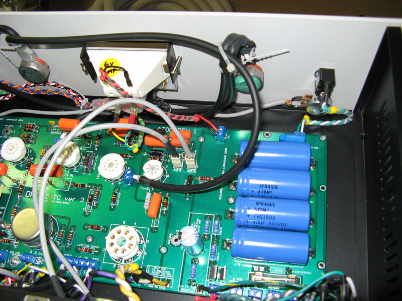
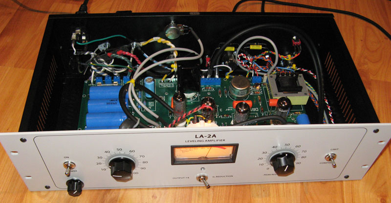
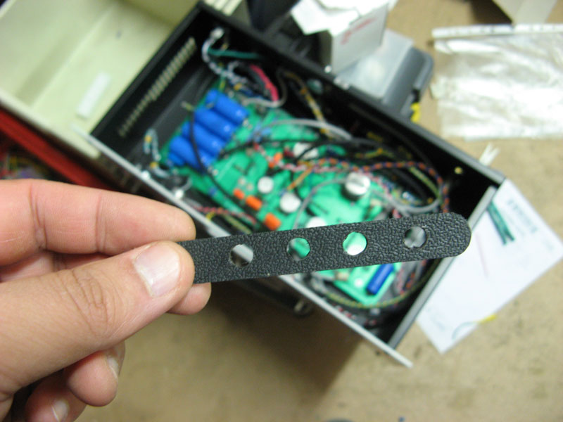
Interchangeable caps system for C1, C2, C3 so that I can change caps for different flavours. Using those NOS big chunky silver caps.
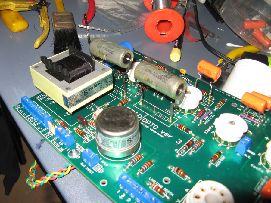
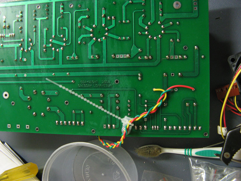
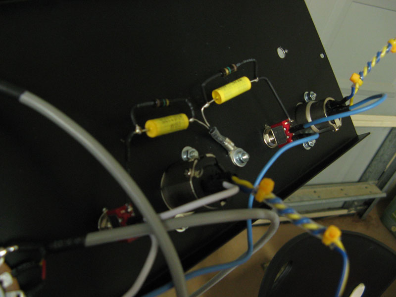
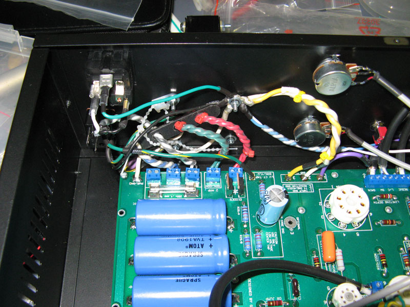
Implemented Output Transformer switching system as shown by braided cable portuding from the bottom of the PCB board.
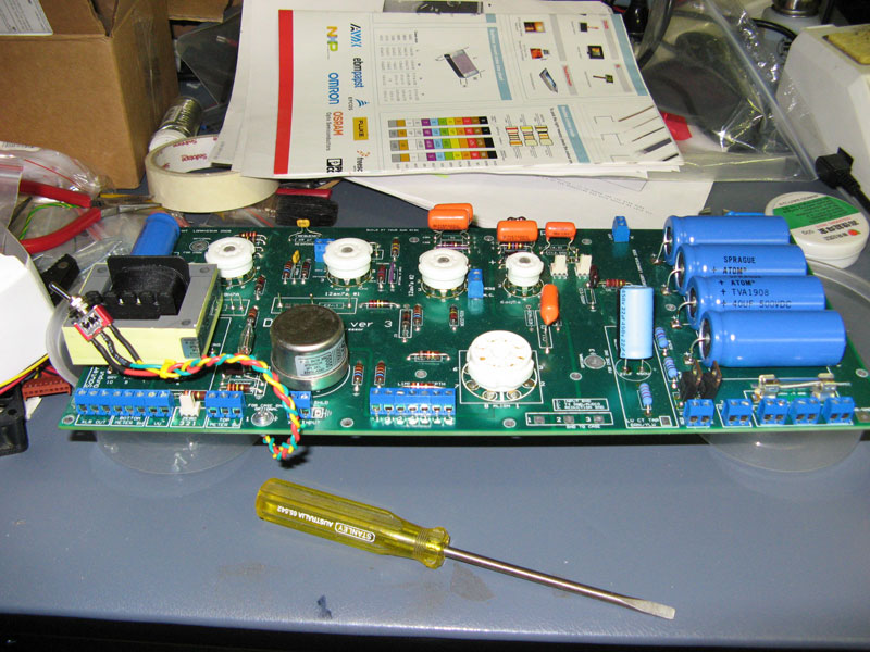
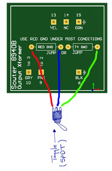
Wiring used for the Output Transformer switching system
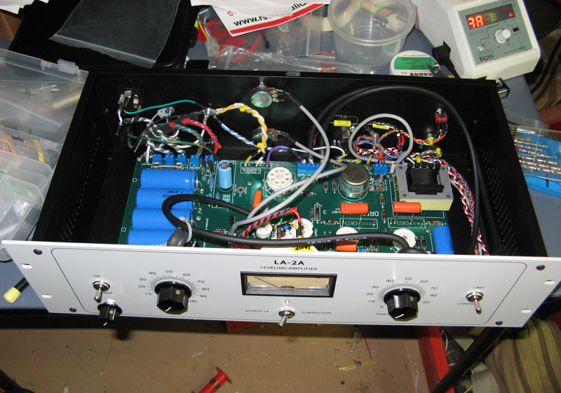
Wiring up
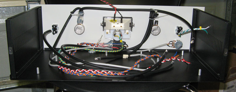
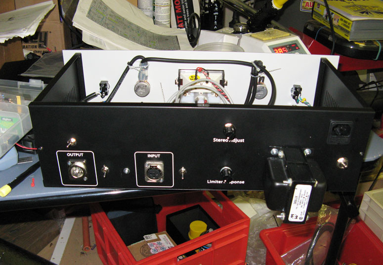
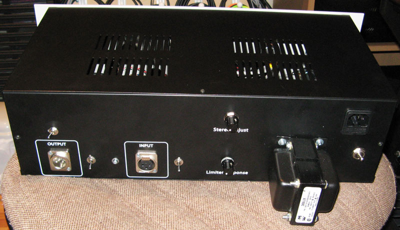
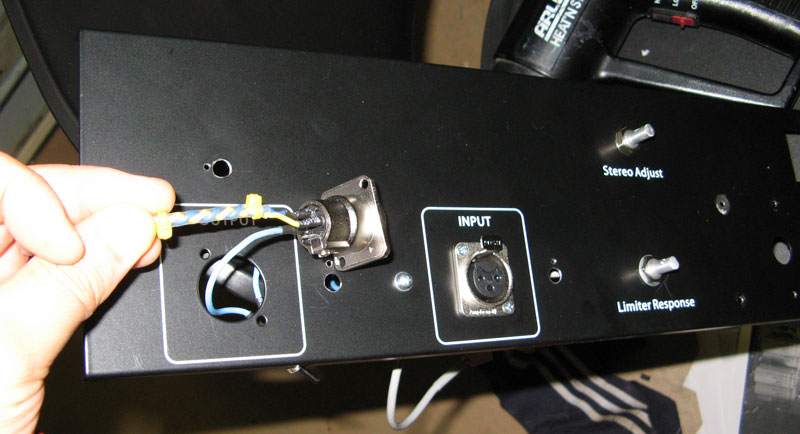
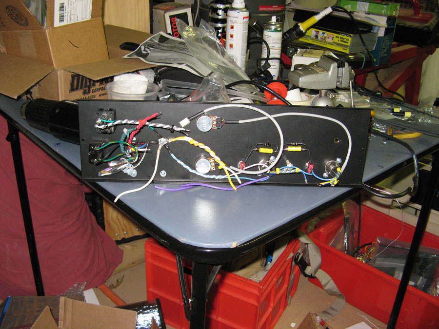
Remove rear panel of rack case to finalize wiring for rear panel section.
Wiring XLR cabling must be done by feeding cables thru and soldering XLR into place.
Drips ground lift system.
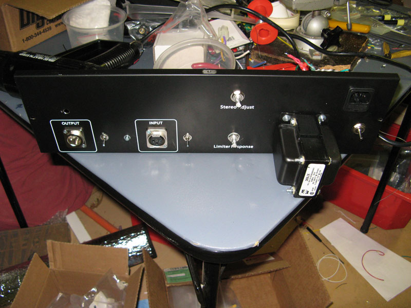
Rear panel ready.
The lab. Working up to 6-10am these past few weeks trying to get these beasts completed. Garage is not the best place to do DIY I have realised. Frrrrreeeezing! 8)
Clear table is best to prevent scratching your case... eh.
Printed pics to reference from.
Preparing case for Drips pcb board. For setting PCB mount, best to drill a hole one at a time then re-align PCB, mark next hole then drill and so on.
eg.
Push bolt thru bottom case so that it portrudes and you can align your PCB board using that portruding bolt.
Place PCB on top of bolt and then mark the next hole while pushing the board flat since I had a slight warp on my board which straightens up once the PCB board is mounted properly.
Solder components
Interchangeable caps system for C1, C2, C3 so that I can change caps for different flavours. Using those NOS big chunky silver caps.
Implemented Output Transformer switching system as shown by braided cable portuding from the bottom of the PCB board.
Wiring used for the Output Transformer switching system
Wiring up
Remove rear panel of rack case to finalize wiring for rear panel section.
Wiring XLR cabling must be done by feeding cables thru and soldering XLR into place.
Drips ground lift system.
Rear panel ready.

")