Kingston said:
You have an oscilloscope right? Track B+ line while playing audio. Is it a straight line? If it dips full 10 volts you still wouldn't see a change in performance, even when you might assume it's a bad thing. A bigger reservoir cap most likely doesn't do anything. I'm using B+ regulators with only a single 4.7uF poly cap these days, for example.
bruce0 said:
You mention the 1538, original G9 schemo called for the 1528. I am assuming you are using the 1538.
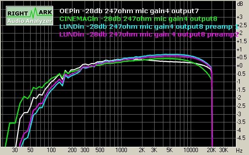
I didn't realise you had changed it to LL1538 for the GIX51X. I'm using LL1528. Thing is, LL1538 has a completely
amazing frequency response, all the way to 100khz! It performs even better than LL1528 looking at the datasheets.
There is
nothing in the input stage that makes the bass cut you are seeing. I've been trying to explain this so many times already. What I don't get is that when you are measuring the whole signal path of G9 and see a bass cut, why have you automatically assumed it's the input transformer?
Please measure the input transformer in complete isolation (or with the line input pad) if you have trouble understanding what I'm saying.
Measured 3V RMS dip approx, Only visible at low frequencies (below 200Hz), but I am not sure what the peak dip is...
Probably no effect. Your 4.7uF poly sits next to the 100uF PSU reservoir in a G9?
Yes, I agree we don't seem to be communicating on this point. It is probably my inexperience, or lack of clarity.
Clearly put:
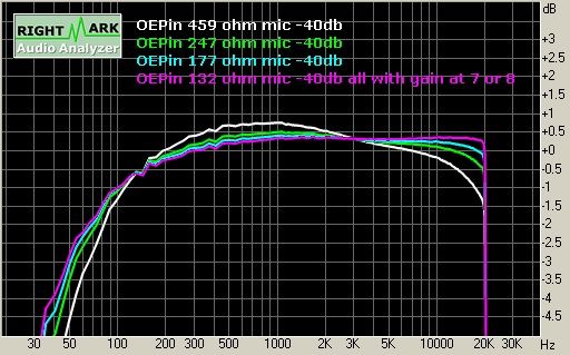
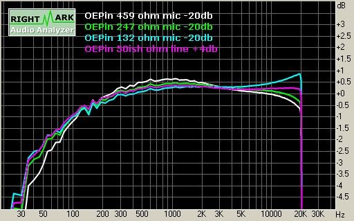
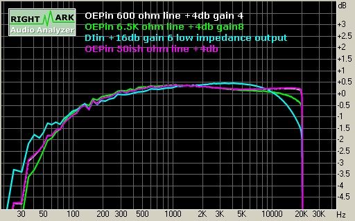
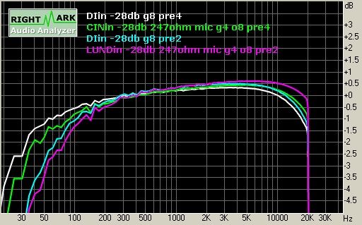
1) I noticed, measured and documented a difference in performance between the different input Transformers I have. I am endeavoring to explain why, and/or improve the laggards.
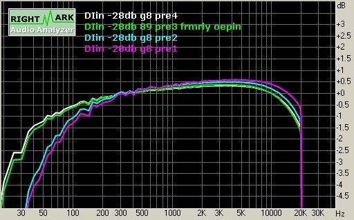
I think you will agree the pre's measurements should not be different solely because of input transformer if they are not having an effect (EXCEPT for the inherent differences in their capabilities). And it makes little sense that an OEP should perform better than an LL1538 as is currently the case here.
Hmmm. Perhaps I should be testing the response without an output transformer.
2) I realize, recognize, agree with, acknowledge and appreciate the low frequency rolloff issues you have documented with respect to the SRPP output stage. I appreciate your explanation. I have not yet begun to approach those issues, and was planning on looking at it after I did #1 above.
I think I am hearing you clearly. I understand that you suggest I address the "big obvious improvement" before I address the "little tweaky issue" that I am working on. Thank you for your suggestion, and I will take a look at the "big" issue, but first I want to address the "little" issue. I explain why this order below, if you care to know why.
I genuinely appreciate your comments, and apologize if I am causing you frustration (many of my teachers in the past had the same experience, and I think it is my fault).
Bruce
Explanation: Why am I working the input trafo issues first. Because they should not be different in noise, distortion and performance from their respective specs and capabilities. If I can make them perform to spec, I think I will have usable interesting colors in these preamps, and portable to boot. This is because I believe the Pre's will work for vocals and most strings with or without the extended low end, but I want the to have "color" not Jackson Pollack style distortion due to the input trafo setup.
bb


")