GSSL HELP THREAD!!!

GroupDIY Audio Forum

Help Support GroupDIY Audio Forum:

This site may earn a commission from merchant affiliate links, including eBay, Amazon, and others.
Excuse me for asking, but I can not find any information for some of the Turbo PCB board  for sale?
And Those Where can I order? And where can I order these?

Thanks
Hugo
 
Hi Folks

I read the whole Post but couldn't find an answer to get my specific transformer wired correctly. So, could you please help me?
After a bunch of Jeff's APIs and a passive summing box the SSl is my first DIY-Project on high voltage. I don't like to get fried  ;D
Please help me...

Transformer-Infos:

Primary
blue-brown: 0-230V


Secondary
black-red:  0-15V
orange-grey: 0-15V

Where do the Secondary-Wires have to be connected?
I live in Switzerland, which means 230V.

Thanks a lot

Urs


Attachments

  • Wiring.jpg
    Wiring.jpg
    191.3 KB · Views: 43
Finch78 said:
Transformer-Infos:

Primary
blue-brown: 0-230V


Secondary
black-red:  0-15V
orange-grey: 0-15V

Where do the Secondary-Wires have to be connected?
I live in Switzerland, which means 230V.

Thanks a lot

Urs

If I remember correctly the middle pin is the ground, but why don't you trace the ground if you are not sure.  15v ungrounded(ac) and ground  if you are using and off board xformer. plug your xformer into an outlet and use a meter to read your secondary to make sure you are getting proper voltages befor you hook it up ;)
 
Hi migidee

Oops - I will measure the voltages, sorry to not think of the most apparent step. But to double check: this means that in my case the black and orange wires go together in to the middle pin, right (Number 2 in my drawing)?
And it  doesn't belong if red/grey goes to Nr. 1 or 3 and vice versa, right?

Urs
 
Finch78 said:
Oops - I will measure the voltages, sorry to not think of the most apparent step. But to double check: this means that in my case the black and orange wires go together in to the middle pin, right (Number 2 in my drawing)?
And it  doesn't belong if red/grey goes to Nr. 1 or 3 and vice versa, right?
Hi Urs, link transformers secondary black to grey wire, giving you the center tap connection.
Red or orange for the No.1 or 3 pcb connection doesn't matter, as transformer secondary voltage is AC.
When measuring the transformers secondary AC voltages for confirmation without load connected, these will read a little higher.
 
Hi, i need some help with my gssl...i've finished the build with 2 x SuperSC boards and turbo mode switchable...i've got the unit working and passing audio fine. My problem is that only the left channel signal is causing compression...when i mute the left channel input and leave the right channel open there is no compression, but audio passes fine on the right channel...when i mute the right channel and leave the left channel open the unit compresses normally on the left channel...i can't guarantee that the turbo board is working ok, assuming that it needs both channels input to be working properly...

any help is appreciated!

george
 
hi,

I've a problem with the Ratio of my GSSL. In Ratio 2:1 and Threshold -20 at fast Attack and fast Release all seems to be normal. But in Ratio 4 or 10 it sounds crack on each snare hit or bass drum hit, it's as it don't compress the first peak in fast Attack. I've checked all resistors for Attack and Release, all is fine. At Attack 10ms and 30 ms it sound normaly.
Did somebody have the same problem or any idia?

Thanks

Danny


Here is a link where you can download a file, the first track is gssl in bypass on a drum group. the 2nd track is ratio 2, threshold about -10, attack 0.1ms release 0.1s, 3rd ratio 4 same attack and release as before, 4rd ratio 10, attack release same before. If you look at the track in your DAW you can see the peaks at ratio 4 and 10, ratio 2 looks normaly I think. What do you mean about this?

https://files.me.com/blackpoolpirates/lxpxka.mp3

Thanks

Danny
 
hey guys,

I have a weird problem on one of my GSSLs with turbo fitted...
The unit works fine...meter readings on the turbo board match the mainboard

An issue appears when I have the attack set at .1 or .3, and the threshold sensitivity fully counter clockwise

I get distortion in the right channel, it goes away as I turn the threshold clockwise, or change the attack to a different setting other than .1 or .3

I've attached a sample soundfile where you can hear the problem, then as I adjust the attack it goes away:
https://rcpt.yousendit.com/1197625511/bd795eb86afc35c45380b059318f4241

If I don't have the turbo board connected, the problem goes away.... so I am thinking its something on the turbo board but don't know where. As I said, all readings on turbo board look OK and there are no isses on other attack settings, or when I dont have the threshold fully CCW...

Appreciate any ideas you might have
 
update:

I've just noticed that when the distortion is occuring in the right channel and when measing pin1+14 on the TL074 on the Turbo board, its up at around 17v.... which is too high (I thought it was only designed to run at 15v hence the distortion)??? Then when I change attack setting or adjust threshold it drops below 15v and sound goes back to normal....

-----------

*** i found a 470k resistor in place of the 470R location on the turbo board.... kill me..... i changed it but still have the same problem , any other blackspots worth looking for?
 
frazzman said:
... and when measing pin1+14 on the TL074 on the Turbo board, its up at around 17v...
with a +/-12V supply these pins won't read 17V. Measure again with reference to 0V or get a fresh battery for your multimeter.
For your distortion issues look out for shorts and double check Turbo wiring to (unused) pins/pole at the ratio switch. Double check the connection from the correct side of the 100R resistor at mainboard to Turbo-S/C-C.V.
 
Holiveira said:
What is more advisable to a transformer with  2 x 15V or 2 x 18V (secondary)?
2x 15V AC secondaries will give less power wasted in the 78L12/79L12, especially with additional TURBO board.
 
MikeClev said:
Bob, you have to be careful when wiring those inputs and outputs on the standard GSSL because the + and - are very easy to get mixed up.

Input is on 5 pins:

O + Left.  Pin 2 on left XLR. Goes to left TRS jack tip.
O - Left.  Pin 3 on left XLR. Goes to left TRS jack ring.
O Ground.  Pin 1 on both XLRs. Goes to both TRS jack sleeves.
O - Right.  Pin 3 on right XLR. Goes to right TRS jack ring.
O + Right.  Pin 2 on right XLR. Goes to right TRS jack tip.

Output is also on 5 pins but + and - swapped, and also right and left swapped:

O - Right.  Pin 3 on right XLR. Goes to right TRS jack ring.
O + Right.  Pin 2 on right XLR. Goes to right TRS jack tip.
O Ground.  Pin 1 on both XLRs (should go from XLR to star ground, not to here)
O + Left.  Pin 2 on left XLR. Goes to left TRS jack tip.
O - Left.  Pin 3 on left XLR. Goes to left TRS jack ring.

As you can see, with + and - swapping, and right and left swapping, its very easy to get one of the polarities mixed up. I did exactly that on my first GSSL and had the exact problem you described.

Another bit of advice is to not use a cable that shorts the output cold connection to ground, as this means that the opamp will be dumping lots of current which may cause distortion in the output of the other opamp on the hot pin. On my GSSL I put in two pairs of output jacks, one wired for balanced and one wired for unbalanced connection with the cold/- output not connected to anything.

I hope that helps!

-Mike

Hi all, wiring up xlrs on mine, ignoring the trs connections above, is this correct?

O + Left.  Pin 2 on left XLR.
O - Left.  Pin 3 on left XLR.
O Ground.  Pin 1 on both XLRs (back to main board)
O - Right.  Pin 3 on right XLR.
O + Right.  Pin 2 on right XLR.

Output is also on 5 pins but + and - swapped, and also right and left swapped:

O - Right.  Pin 3 on right XLR.
O + Right.  Pin 2 on right XLR.
O Ground.  Pin 1 on both XLRs (back to main board and to my chassis earth connection)
O + Left.  Pin 2 on left XLR.
O - Left.  Pin 3 on left XLR.

Will be using plastic pcb pillars also. Just want to make sure my grounding is correct, so link pins 1 on inputs, these go back to main board center pin. Linking pins 1 on outputs, these go back to main board center pin and i'll also run a wire from pins 1 back to my chassis ground.
Are these connections fine using unshielded cable, they are very short?

cheers

chris
 
Hi guys,

got a question about the sidechain pcb and how to connect it. do i connect the "com/on/off/pot a/pot b" directly with wires to the frontplate pcb? I saw a photo of it with a potmeter in between, i didn't really understand that...
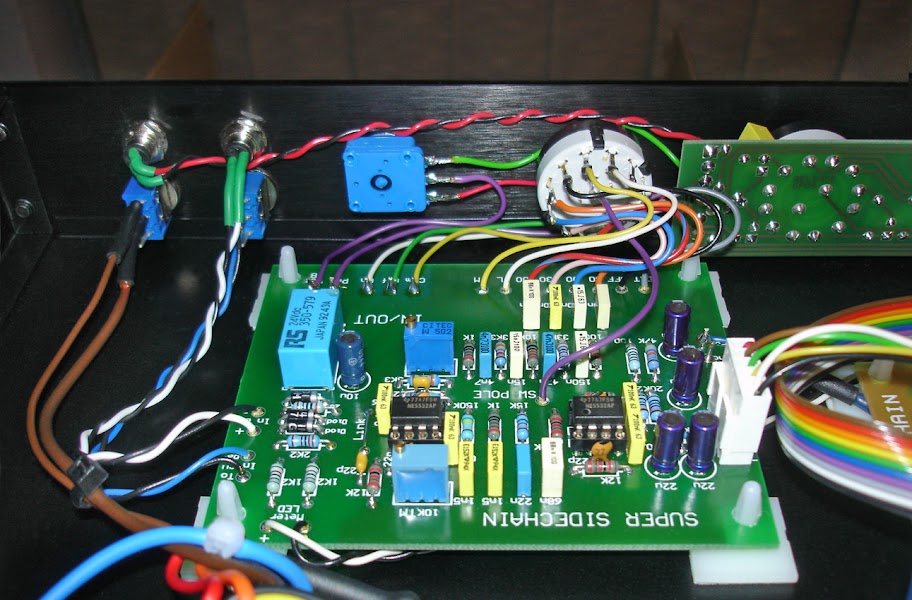
PCB%252520in%252520Situ.jpg


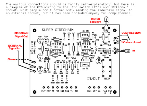
and then there's the connection to the sidechain input. I used TRS instead of XLR. Do i connect the connections on the left (on the pic below) to the tip/ring/sleeve of my jack? i don't understand why it says signal in/signal out...

PCB%252520connections.jpg


The connections at the right top (pic above) "compression/in" is that gonna be the bypass switch?
Can i just use a toggle switch like the one below for that? Do i then just use the outer pins?

miyama1.jpg
 
synnys said:
got a question about the sidechain pcb and how to connect it. do i connect the "com/on/off/pot a/pot b" directly with wires to the frontplate pcb? I saw a photo of it with a potmeter in between, i didn't really understand that...
yes. You could use one wire less (as shown in the pic) by joining the wiper of the makeup pot with 'pot B' directly instead of going back to gssl-control pcb and back to the pot wiper connection.

and then there's the connection to the sidechain input. I used TRS instead of XLR. Do i connect the connections on the left (on the pic below) to the tip/ring/sleeve of my jack? i don't understand why it says signal in/signal out...
yes. With switch in 'External' position your program signal goes to signal out --> R of your TRS plug --> External device to shape your signal, returning to --> T of your TRS plug. Its an insert for your control voltage path. Only using the T would be a Key input for maybe triggering the compression behaviour by only a kickdrum signal. Inserting an external EQ could shape your signal in a way that compression behaviour is less effected by high frequency signals instead. Inserting an external compressor could give you another flavour with the advantage of only one compressor in the audio path instead of daisy chaining different compressors.

The connections at the right top (pic above) "compression/in" is that gonna be the bypass switch?
Can i just use a toggle switch like the one below for that? Do i then just use the outer pins?
yes. You use the switches center pin (pole) and one of the outer pins (throw positions) for switching the relay coil on/off.
 
Back
Top