Help me understand gyrator anode load for tubes

GroupDIY Audio Forum

Help Support GroupDIY Audio Forum:

This site may earn a commission from merchant affiliate links, including eBay, Amazon, and others.

Ilya

Well-known member
Joined
Feb 25, 2005
Messages
752
Location
Moscow
I'm researching various options for replacing anode choke in tube preamp stage.
As far as I can understand, choke basically works as a "sort of" CCS at audio frequencies. I looked into various CCS designs and stumbled upon something called a gyrator anode load. Here is the common schematic of such circuit:
Gyrator-PCB-Rev08-1.jpg

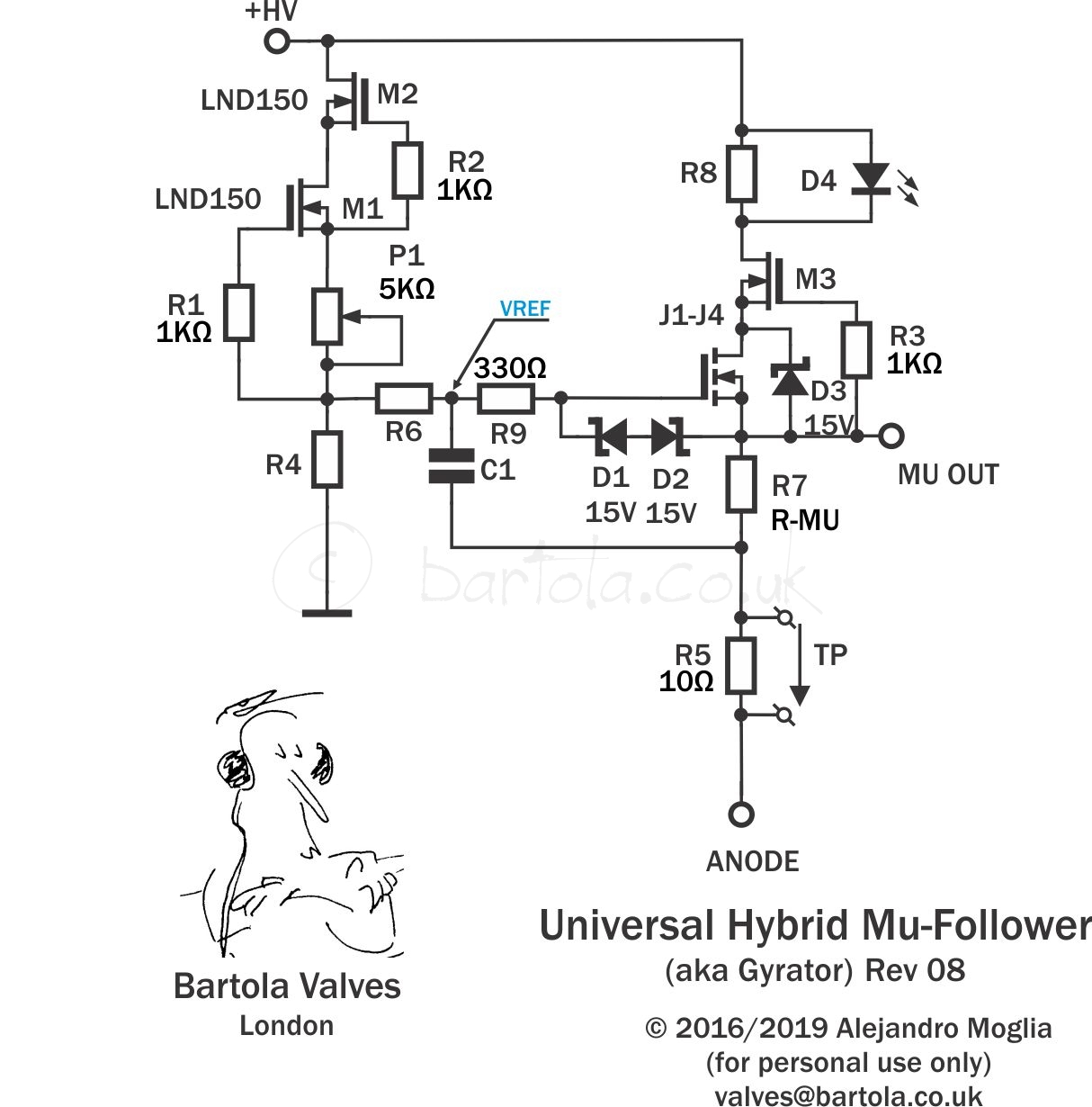
I'm struggling with the righthand part of this circuit. I understand the cascoded CCS to the left, I also suppose that P1 is for setting the correct current for MOSFET zero tempco point, and a way to set it is to read the VREF voltage and adjust P1.
Now, with the righthand part, I really need clarification on R6/C1 and output options. The output can be taken from the tom of R7 or from the bottom of R7. I believe that the top output is the one I should use, but I'm not completely sure.
Also, do I set anode current (or voltage)? Is it dependent on R7 (which is suggested to be approximately 1/gm)?
 
Everything to the left of R6 is a precision voltage reference.

I'm thinking C1 and R6 is the high pass filter in the "gyrator".

Presumlably this is supposed to be a simulated inductor.
In this case, the expected behavior would be that a rapid change in load should result in a change in supply voltage but after time defined by C1 / R6, it will recover to the target supply voltage programmed by P1.

Of course the purpose of using a choke is to isolate a power section from a pre section.
So my guess would be that you connect your power amp to MU OUT and the pre to ANODE.
Or maybe it's the other way around ...
 
Exactly, the left part is a precision Vref that is formed by a precision CCS+R4.
Yes, C1/R6 form a HPF, so a huge value for R6 helps keep the C1 low. I see that changing these values affects the resulting frequency response at the output.
Of course the purpose of using a choke is to isolate a power section from a pre section.
So my guess would be that you connect your power amp to MU OUT and the pre to ANODE.
Or maybe it's the other way around ...
I'm not sure I'm reading this correctly. This circuit is placed in the anode of the tube, it's not the PSU filtering inductor simulation. As described in the circuits designer notes, these points offer different output impedance (with mu-out having a low impedance, and anode out having high impedance). I'm trying to understand why Rmu is selected to be 1/gm.
 
I'm researching various options for replacing anode choke in tube preamp stage.

Don't. Just my view.

As far as I can understand, choke basically works as a "sort of" CCS at audio frequencies.

It does. May I present the original article that introduced the "Mu-Follower" to the world? All is explained there:

https://www.fetaudio.com/wp-content/uploads/2003/09/Mu-Stage.pdf

Thor

PS, I feel the circuit you show is extremely overelaborated without good reason. Here what I use, more or less.

IMG_20230422_211249.jpg

I typically use a low capacitance N-Channel MOSFET (capacitance is the figure of merit for this circuit, the more the lower the tube current).

Resistor dividers using 10MOhm+ resistors to set the Tube's anode voltage (instead of Rg2).

Source resistor (RP) and coupling cap to suit. I often use 10nF Silver Mica and set the source resistor to drop 10V. 1k Gate stopper, 12V Zenner.

What I like about this circuit is that is very suited to "lowish (and safe) voltage" tube circuits.

100V DC is rated "safe low voltage". Leave 20V for the MOSFET, 5V for the source resistor, you have 75V on the Anode, which usually puts us into a good place on the plate curves...
 
Last edited:
Back
Top