Hey guys,
I figured I would post some pics of a project I have been working on. The idea started with a desire to create a vintage looking VU sorta module that slightly resembled my console’s meter bridge. I spoke with Hairball Mike about meters and at that time, he had nothing with a window with the style and size that I wanted. I talked to all of the likely sources and decided to special order meters from Hoyt. The meters themselves are awesome and very solid and heavy. I am told these are the exact same meters they use when they build to order, true “VU” spec meters. I did not want to go down that road so I just ordered the DC meters and took the bridge rectifier into my own fat little hands.
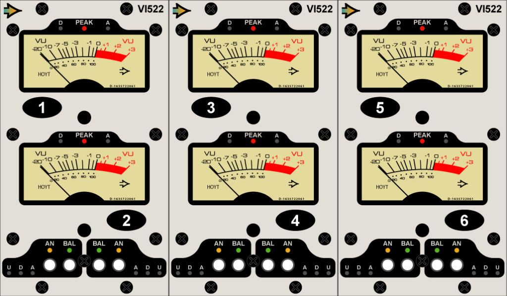
I call the module “VI522”. VI is for volume indicator as it probably doesn’t meet all the required criteria to be a true VU but it’s about as close as you can get without breaking the piggy bank!
I have a 4558 that drives the meter. One half is a 100k Z, balanced circuit where 1.228V of AC will give you 0VU on the meter. The standard VPR pins 8 and 10 are used for this input and are also directly mult’ed to the module slot’s output. You can run a balanced signal thru this module and the original signal will never know the 4558 is hanging there.
The other half of the 4558 is feed an unbalanced signal from pin 9 of the card edge. This is fully VPR compliant, BTW. Pin 9 is easily accessible on my GDIY 508 backplane. This side of the IC has 6dB of additional gain. The idea is to feed it from just before an output transformer in the console. Selecting which side of the 4558 is driving the meter is done via a front panel switch. The signals are actually switched with a relay. This relay can also be controlled by a 0V signal being applied to pin 6 which is the DC pin according to VPR. Why do you ask? This way, one switch can flip multiple VI522 modules from say input channel metering to subgroup metering or what have you. Very important for the console build
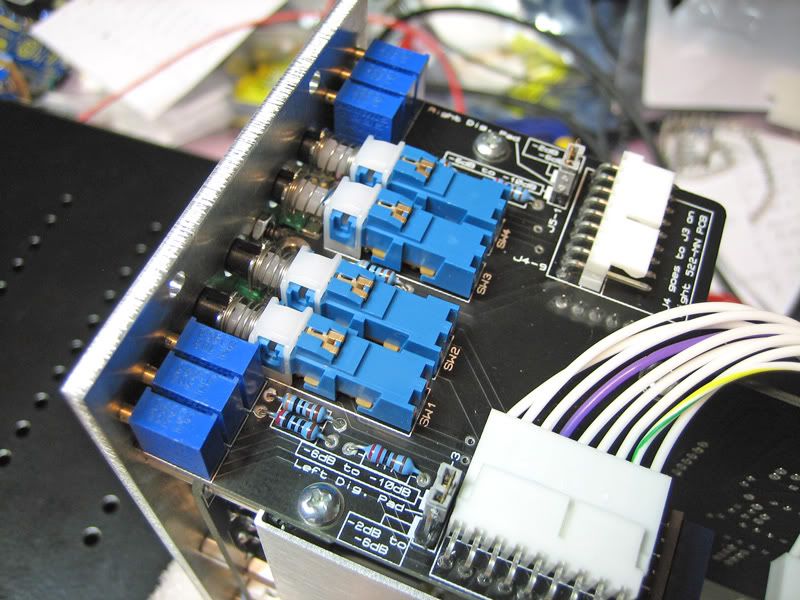
When in “balanced”, mode the other front panel switch will toggle in a pad (more or less) for digital signals. This “digital” selection has it’s own trimmer so the user can set their dBFS to whatever they want. I have two ranges for this “pad” that are selected by a shunt jumper underneath the switch PCB. Basically, the first setting will give you a pad range of 2dB to 6dB and the second setting is 6dB to about 10dB. This way, I am not the one deciding what dBFS level = 0VU…you are!! Funny enough, I talked to 3 of my closest friends about this and got 3 different answers!
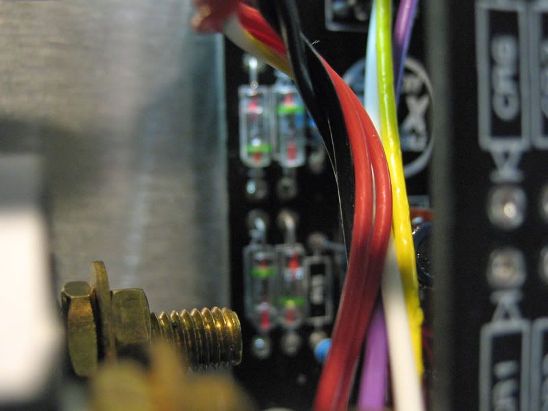
I also have a full wave peak detection circuit that hangs just before the typical 3k6 series R, which is just before the germanium diode bridge. This is a somewhat simple circuit that uses a 1458. This will illuminate the red LED that is just above the respective channel’s meter. The point where the LED fires follows the analog/digital switch. So, you can have one setting for your “digital” preset and a fully independent setting for your “analog” preset. Maybe you will have your analog peak LED light at +9dBu and your digital setting light at –2dBFS? No problem. These are front panel trimmed just to the left and right of the peak LED.
Down near the bottom, there are 3 more front panel trimmers for each channel. One is for the balanced digital setting, one is for the balanced analog setting and the last is for the unbalanced input.
This morning I ordered my second Rev of the 3 boards. I had a few minor things to tweak but nothing big. Anyhow, enough BS, here are some pics!
Peak LED set to +6dBu

Being fed a +4dB signal

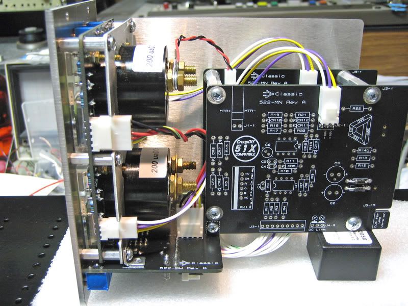
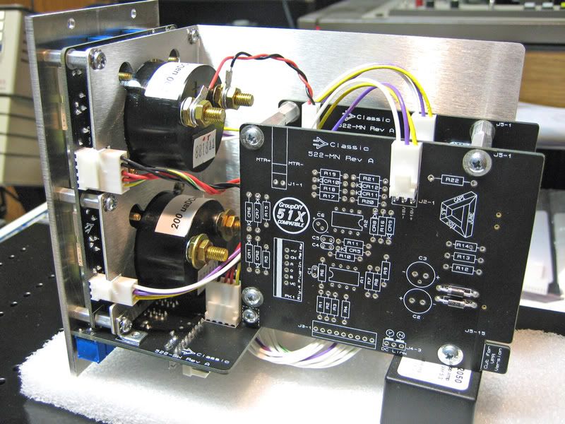
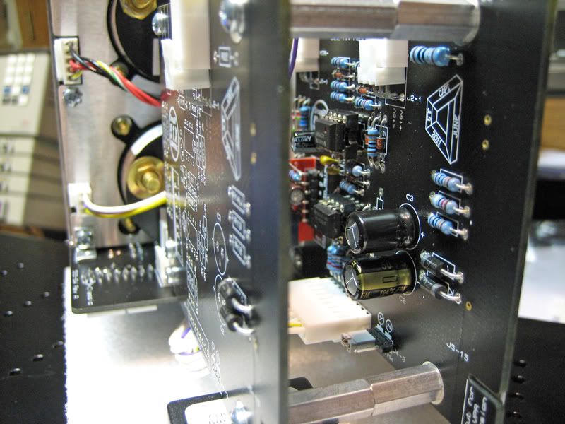
I only built out one of the main boards for testing. I didn’t want to waste time since it will likely make it’s way into the circular file, Rev A.1 coming and so on…


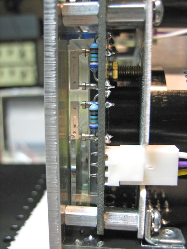
Close look at the side

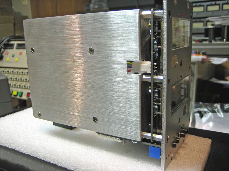
I call this the “cleavage” shot, looking down the shirt of…

The caboose

L-bracket side. Here you can see that the window of each meter is thru the faceplate. Actually, slight proud of the faceplate.

Light pink underbelly…

And lastly, I finally found the confounded germanium diode bridge!!
Cheers for now, Jeff
I figured I would post some pics of a project I have been working on. The idea started with a desire to create a vintage looking VU sorta module that slightly resembled my console’s meter bridge. I spoke with Hairball Mike about meters and at that time, he had nothing with a window with the style and size that I wanted. I talked to all of the likely sources and decided to special order meters from Hoyt. The meters themselves are awesome and very solid and heavy. I am told these are the exact same meters they use when they build to order, true “VU” spec meters. I did not want to go down that road so I just ordered the DC meters and took the bridge rectifier into my own fat little hands.
I call the module “VI522”. VI is for volume indicator as it probably doesn’t meet all the required criteria to be a true VU but it’s about as close as you can get without breaking the piggy bank!
I have a 4558 that drives the meter. One half is a 100k Z, balanced circuit where 1.228V of AC will give you 0VU on the meter. The standard VPR pins 8 and 10 are used for this input and are also directly mult’ed to the module slot’s output. You can run a balanced signal thru this module and the original signal will never know the 4558 is hanging there.
The other half of the 4558 is feed an unbalanced signal from pin 9 of the card edge. This is fully VPR compliant, BTW. Pin 9 is easily accessible on my GDIY 508 backplane. This side of the IC has 6dB of additional gain. The idea is to feed it from just before an output transformer in the console. Selecting which side of the 4558 is driving the meter is done via a front panel switch. The signals are actually switched with a relay. This relay can also be controlled by a 0V signal being applied to pin 6 which is the DC pin according to VPR. Why do you ask? This way, one switch can flip multiple VI522 modules from say input channel metering to subgroup metering or what have you. Very important for the console build
When in “balanced”, mode the other front panel switch will toggle in a pad (more or less) for digital signals. This “digital” selection has it’s own trimmer so the user can set their dBFS to whatever they want. I have two ranges for this “pad” that are selected by a shunt jumper underneath the switch PCB. Basically, the first setting will give you a pad range of 2dB to 6dB and the second setting is 6dB to about 10dB. This way, I am not the one deciding what dBFS level = 0VU…you are!! Funny enough, I talked to 3 of my closest friends about this and got 3 different answers!
I also have a full wave peak detection circuit that hangs just before the typical 3k6 series R, which is just before the germanium diode bridge. This is a somewhat simple circuit that uses a 1458. This will illuminate the red LED that is just above the respective channel’s meter. The point where the LED fires follows the analog/digital switch. So, you can have one setting for your “digital” preset and a fully independent setting for your “analog” preset. Maybe you will have your analog peak LED light at +9dBu and your digital setting light at –2dBFS? No problem. These are front panel trimmed just to the left and right of the peak LED.
Down near the bottom, there are 3 more front panel trimmers for each channel. One is for the balanced digital setting, one is for the balanced analog setting and the last is for the unbalanced input.
This morning I ordered my second Rev of the 3 boards. I had a few minor things to tweak but nothing big. Anyhow, enough BS, here are some pics!
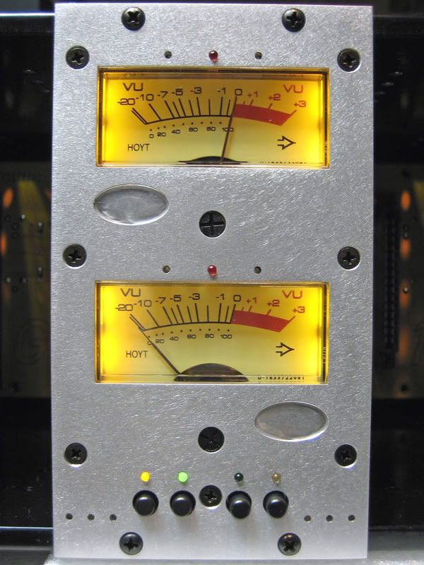
Peak LED set to +6dBu
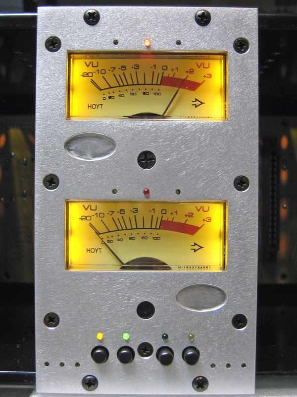
Being fed a +4dB signal
I only built out one of the main boards for testing. I didn’t want to waste time since it will likely make it’s way into the circular file, Rev A.1 coming and so on…
Close look at the side
I call this the “cleavage” shot, looking down the shirt of…
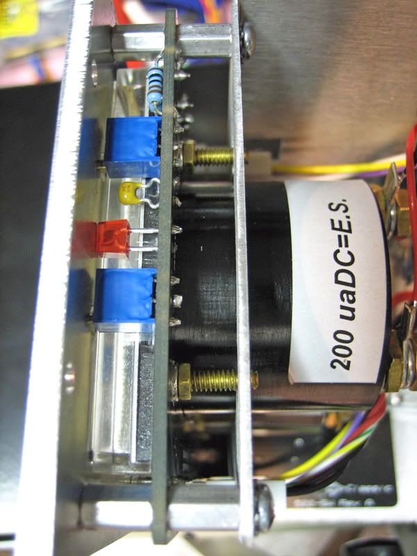
The caboose
L-bracket side. Here you can see that the window of each meter is thru the faceplate. Actually, slight proud of the faceplate.
Light pink underbelly…
And lastly, I finally found the confounded germanium diode bridge!!
Cheers for now, Jeff