I didn’t think I would be around to start another “from scratch” project, but it seems I am in remission, so life goes on as normal. My last from scratch project was a departure for me to make a basic transistor amp, but it was a total failure! Since then I have rebuilt a Marantz Hi-Fi amp with a new circuit and it works beautifully so confidence is restored! I will post that separately.
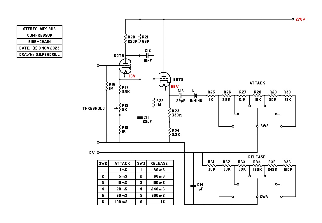
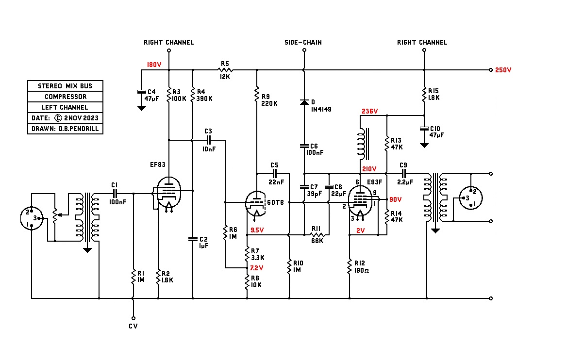
My friend asked me for a simple mix-bus compressor using some tube circuits that have given him some good results in the past. It won’t need much more than about 3dB compression, so this opens up other options that we couldn’t use for deep compression. The main effect will be to warm up the sound with transformers and tubes and to glue the mix together.
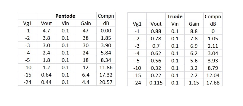
I have chosen to use the special EF83 tube for gain reduction, it maintains a near constant anode current flow down to -10V, so it should not “thump”. This tube was used in Grundig tape recorders for many years and it does not need to be push-pull or work into an interstage TX. I have attached the spec sheet and what I'm referring to is on page 10.
I start these projects with a scale drawing of the front panel, sorry the contrast is not very strong.
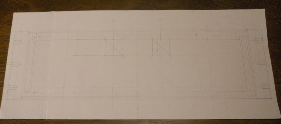
This helps me to calculate the width and height of the box behind the front panel, then I can start cutting metal to size.
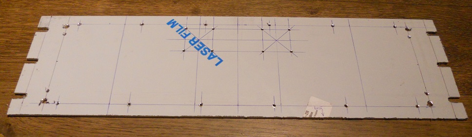
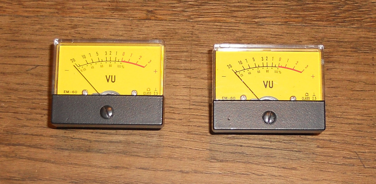
As you can see, it will be a 3u box, I found a couple of nice vintage german VU meters which will be fitted where X marks the spot.
best
DaveP
My friend asked me for a simple mix-bus compressor using some tube circuits that have given him some good results in the past. It won’t need much more than about 3dB compression, so this opens up other options that we couldn’t use for deep compression. The main effect will be to warm up the sound with transformers and tubes and to glue the mix together.
I have chosen to use the special EF83 tube for gain reduction, it maintains a near constant anode current flow down to -10V, so it should not “thump”. This tube was used in Grundig tape recorders for many years and it does not need to be push-pull or work into an interstage TX. I have attached the spec sheet and what I'm referring to is on page 10.
I start these projects with a scale drawing of the front panel, sorry the contrast is not very strong.
This helps me to calculate the width and height of the box behind the front panel, then I can start cutting metal to size.
As you can see, it will be a 3u box, I found a couple of nice vintage german VU meters which will be fitted where X marks the spot.
best
DaveP
")