


Hi all,
I received the PCBs today with thanks - nice work")
I'd like to hook them up to some drip electronics fourseven preamps. Those guys are powered by a 370bx hammond transformer and the violet wire is unused by the PCB and specified as 50V. Can I get my power from there? The wire is declared as "Bias Tap with High Voltage C.T. Grounded" which I have no idea about.
The transformer is defined as:
550V C.T. @ 58ma.
5V C.T. @ 2A
6.3V C.T. @ 2A
And this is the schem:
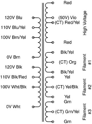
can I get my power between violet and ... red/yellow?
Cheers,
B.
I received the PCBs today with thanks - nice work
I'd like to hook them up to some drip electronics fourseven preamps. Those guys are powered by a 370bx hammond transformer and the violet wire is unused by the PCB and specified as 50V. Can I get my power from there? The wire is declared as "Bias Tap with High Voltage C.T. Grounded" which I have no idea about.
The transformer is defined as:
550V C.T. @ 58ma.
5V C.T. @ 2A
6.3V C.T. @ 2A
And this is the schem:
can I get my power between violet and ... red/yellow?
Cheers,
B.

