Ribbon Mic Dissection Pictures

GroupDIY Audio Forum

Help Support GroupDIY Audio Forum:

This site may earn a commission from merchant affiliate links, including eBay, Amazon, and others.
http://microphonium.blogspot.com/2006/05/fisher-phantom-powered-ribbon-mic-two.html
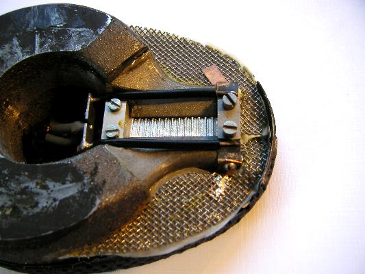
is a large image (or way to get to it) with better detail where you can see the machining marks on the tapered pole pieces that have been silver plated over steel. That aerial frame arrangement is a little wiggly. We didn't need to use the adjustment screws to get the ribbon into a good position and tension.

Indeed it is a rare bird and very interesting. The ribbon is tapered and today we put in a replacement as the original was stretched. While the ribbon was out the field was measured at the top, middle and bottom of the gap and found to be a fairly uniform 500 Gauss. Quite a weak field. Yet the onboard amplifier is enough to get a good signal, albeit with some noise. The stray fields around this mic are almost too high to handle, and there is little magnetic or electrical shielding.

Little thought has gone into the acoustic coupling of sound and ribbon, with the obvious exception of the tapered pole pieces. (edit: what I mean by this is there is nothing like an acoustic resistance or matching element in the near field of the ribbon save the pole pieces and of course the ribbon itself. Instead of "little thought" I should simply say "little work")

Overall, the machining is good, but the assembly is messy, and home-made. A DIN connector supplies plus and minus 15V from an external supply, and conducts the amplified signal to an external UTC transformer in yet another, separate enclosure.

I will capture some spectral data and put that on the blog. It has plenty of signal around 15 KC and is quite flat over its range.

CJ, fascinating fields - especially the blue rings - thanks - your doing?

Bbob


http://microphonium.blogspot.com
 
[quote author="BBob"] A DIN connector supplies plus and minus 15V from an external supply, and conducts the amplified signal to an external UTC transformer in yet another, separate enclosure.[/quote]

So, does the mic have an internal step-up transformer, or is it electronically balanced and amplified with transistors only? If it does use an internal transformer, then I wonder on it's performance. I'd maybe bypass the electronics....

I will capture some spectral data and put that on the blog. It has plenty of signal around 15 KC and is quite flat over its range.

Cool. Again, I wonder about the HF roll-off characteristics since at the thicker end we will see the response roll off earlier, whilst the thinner end will maintain its HF response for longer.

I'm guessing that if the poles get thinner linearly (which it looks like they do (ie. not curved)) then we could theoretically calculate this response which might be fun... I'd be interested in how it rolls off compared to the usually theoretical 6dB / octave of most ribbon mics.
 
The blue rings are a real mag field pic.
Notice the eddy currents.

I was reading someting the other day that might be wrong, but it talked about a moving coil wanting a "lower" impedance transformer winding to wirk into rather than a higher, like you see with most electrical signals.
Remember, this is a magnet. So maybe maximum "current" transfer is the goal with a 57 ype mic motor.
Might change the way we view mic transformer designs.
The 57 had a 1.5 ohm pri, very low ohms.
Ribbon is a mag motor too, so...
I will go back for that article.
It was in AES. Altec came out with a dynamic that looked like the sm 57.
This waqs before Shure.
cj
 
Cool eddy currents.

I bet Charles Fisher knew something about that when he designed this motor unit posted in excruciating detail for your viewing pleasure at


http://microphonium.blogspot.com/2006/05/fisher-phantom-powered-ribbon-mic-two.html


Bbob


http://microphonium.blogspot.com
 
Bump.

Bob's ribbon microphone blog is interesting at the moment.

Check those Oktava toroidal ribbon transformers!

http://microphonium.blogspot.com/
 
I think this is a piezo mic, but not sure(you can move this post if you feel it doesn't belong here). Can someone tell? I don't have the external transformer :sad: somebody know what transformer should I choose? Dont' think I can plug it right away in my preamp, can I?
It looks good.

cheers,

Nicolas

mic1.jpg

mic2.jpg

mic3.jpg

mic4.jpg

mic5.jpg

mic6.jpg

mic7.jpg
 
Just saw this excellent photo of the innards of an STC 4038 at a German website:

restoration_STC__new_ribbon__pic_3__big.jpg


Also, I'd like to get my hands on one of these:

restoration_RCA_77DX__new_ribbon__pic_2__big.jpg
 
[quote author="tony dB"]what does that RCA-tool exactly do?
Is it a ribbonmaker?[/quote]

Yes - it's a ribbon corrugator. Makes flat pieces of foil go "wavy".
 
Here's a very old one. It's a Selmer form the 30's or 40's.

Things to note: piston type ribbon corrugation, box magnet assembly with hole cut-out for rear sound path and relatively large step-up transformer.

The ribbon is actually in fairly good condition for its age - perhaps it was reribboned not that long ago.


Years later, an answer....


The Charles Fisher mic has a transformer input. I bypassed the whole thing and got the same curve with one of our transformers. Despite the low field, the long ribbon made up for it some, and the output was OK.

I am currently working the design for some very thin Roswellite, about 300 nm. It's too bad that we don't have room temperature superconductors, yet.

Who will be at Potluck in Nawlins? I would much rather go as an attendee this year, as I missed all the sessions standing at the booth. Guess I will hire someone through a temp agency again.

Bob

http://microphonium.blogspot.com
 
Ooh! My thread is still alive.

Excellent dissections, gentlemen. I am proud of you all.

The magic eye looks astounding.

z50 xx
 
Dragging this out of the distant past... I've just mended the links above so you can now see the pictures again.

Anyway, here are some photos of inside an Oktava ML17... the front:

IMGP4061.jpg


This is a bit like a mini version of the ML11m (see page 5!), and like the ML11 is cardioid(ish) in pattern, with an acoustic labyrinth behind the ribbon assembly. This had come away, so I took a photo before gluing it back in place. It has two rectangular holes with gauze glued over. Presumably this is to tweak the frequency response and control the pattern. Toroidal transformer again, but no extra inductor/cap like the ML11m.

Rear...
IMGP4059.jpg


The magnet assembly looks to be identical to the ML16 (which is figure of 8).

The black cylinder in the middle of the mic is a plastic block - I was a bit surprised by that. It seems a bit pointless actually -  Maybe just to make the mic bigger.

( More photos at http://www.xaudia.com/xaudia/Galleries/Pages/Oktava_Lomo.html )

z50
 
Curiouser...

I wonder if there were official variants. Is yours just marked ML17? The brass 'labyrinth' slots into a circular hole in the base plate. Does yours at least have a hole?
 
zebra50 said:
Curiouser...

I wonder if there were official variants. Is yours just marked ML17? The brass 'labyrinth' slots into a circular hole in the base plate. Does yours at least have a hole?

I'll take a look when I get a chance. Nice mic with a fresh ribbon.
 
Finally, I get to show this off to some folks who might give a hoot...
LA yard sale in the '90s. Some girls were trying to give me a spinet piano that had been owned by an uncle who had lamentably passed on. It was in a studio on a small hillside and they didn't want to carry it down. I didn't want it, but they had a really nice, heavy triangular bottom Atlas mic stand in perfect condition. So I asked how much. "Just take it..." they said. Wrapped around the bottom of the stand was a cable leading to behind a desk. I pulled on it, and out came the mic below, which I held up by the cable like a dead rat.
"How much for this?"
"Just take it."
They also gave me a old stereo Dynaco preamp he had built from scratch which contained 5 working Mullard 12AX7s, and even helped me find the literature for all of this stuff.
Best yard sale ever. Thanks ladies, wherever you are...
It has a bit of corrosion on one of the ribbons which seems to add a small amount of noise to one channel, but I have no idea how to dismantle it without destroying it.
Otherwise it works fine and has been used for a number of recordings over the last decade. Combined with my Royer-modded MXL V67 it makes a fantastic live recording.
I once mentioned to Mr. Royer at NAMM that I had an old B&O ribbon mic, and he smiled at me like the cat that ate the canary.
 

Attachments

  • B&O.jpg
    B&O.jpg
    30.8 KB · Views: 33
Hi,
    I have two of those, its a BM5, them bottom half alone is called a BM6, the top half is removable and is called a BM7, together its a BM5. I'm sure there's many people that could help you, I had mine gone over by Stephan Sank in Arizona, specializes is ribbon mics, and am very pleased with his work,  just thought I'd pass the info along.

  (  BM translation for " Band - ( ribbon )  Microphone "
 
Back
Top