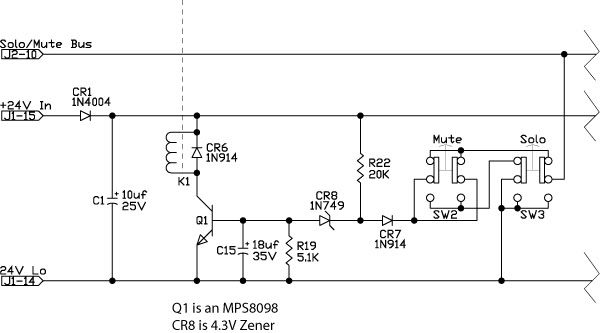
that's the circuit used in older API boards as their relay driver. it's useful because the input is active low, and it is several volts above ground (because of the zener) so you can have several diode drops in the path to ground, which is useful when you have some complex logic function that depends on several conditions being true.
I say older, because my experience was with a 32x24 in the mid 1970s. In these boards, there was a large push button in the center of the meter bridge that activated the solo-in-place system. Essentially what happened is that any channel that wasn't solo'd was muted, and pressing the solo button on a channel grounded the SIP bus while removing that channel from the global mute bus. It's been a long time since I looked at the schematic (which I still have), so next chance I get, I'll look and figure it out further. The advantage to this destructive solo system is the signal took the exact same path to the 2 mix that it would during normal operation. This can be useful, say if you're doing something at bus level and need to hear what it's doing to a particular signal.
Muting in these consoles was an analog switch board; they called it a "soft switch" that used a pair of FETs in a series/shunt arrangement. The soft switches were problematic as I recall, and eventually they were replaced with relays by the studio's maintenance dept (this studio actually had maintenance techs on staff). I had to reverse engineer the circuit board to get the schematic, which I then sent to API marked, "is this correct?" and they responded by sending the blueprint. (they had feigned deafness at earlier requests).
The majority of other switching functions in these consoles were relays.
") Anyhow, it is for mute and destructive solo. Some minor rework would easily provide a dedicated stereo solo bus for non-destructive SIP. The parts are cheap and plentiful. Works like a dream. I like the TQ2's. Q1 is an NPN.
Anyhow, it is for mute and destructive solo. Some minor rework would easily provide a dedicated stereo solo bus for non-destructive SIP. The parts are cheap and plentiful. Works like a dream. I like the TQ2's. Q1 is an NPN.